Functional Architecture Design and Data Flow Diagrams in Industrial Information Systems

The chapter delves into the fundamentals of structured analysis techniques such as data flow diagrams and structured analysis and design technique. It emphasizes the graphical notations used for depicting information flows within enterprise processes. Different methodologies like IDEF0 and SADT are discussed, highlighting their relevance in capturing, manipulating, storing, and distributing data in industrial information systems. The distinction between DFDs and system flowcharts is elucidated, along with the role of DFA in modeling business processes.
- Industrial Information Systems
- Data Flow Diagrams
- Structured Analysis
- Functional Architecture Design
- IDEF0

Download Presentation

Please find below an Image/Link to download the presentation.
The content on the website is provided AS IS for your information and personal use only. It may not be sold, licensed, or shared on other websites without obtaining consent from the author. Download presentation by click this link. If you encounter any issues during the download, it is possible that the publisher has removed the file from their server.
E N D
Presentation Transcript
King Saud University College of Engineering IE 462: Industrial Information Systems Fall 2018 (1st Sem. 1439-40H) Chapter 4 Structured Analysis and Functional Architecture Design p2 DFD i - Fundamentals Prepared by: Ahmed M. El-Sherbeeny, PhD 1
Lesson Overview Modeling IIS (p1) Integrated Computer-Aided Manufacturing Definition 0 (IDEF0) (p1) Data Flow Diagram (DFD) (p2) 2
Functional/Process Modeling Data Flow Diagram (DFD) 3
Functional/Process Modeling Remember: two methodologies for designing a functional architecture, known as structured analysis techniques: o data flow diagrams (1979), widely used by information system professionals in all industries o structured analysis and design technique (SADT) (1988), adapted for manufacturing enterprises under the name integrated computer-aided manufacturing definition 0 (IDEF0) o Both methodologies are based on graphical notations used to describe information flows among processes of the enterprise being documented 4
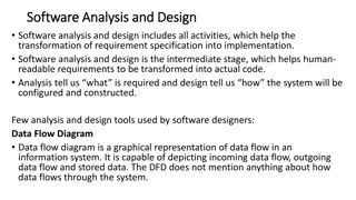
Functional/Process Modeling Graphically represent the processes that capture, manipulate, store, and distribute data o between a system and its environment o and among system components Useful for depicting purely logical information flows DFDs differ from system flowcharts which depict a procedure (see next slide) 5
DFDs vs. IDEF0 Data Flow Diagrams (DFD), aka Data Flow Analysis (DFA) is an alternative to IDEF0 that is widely used in all industries, both in modeling: o manufacturing, and o service processes and operations It differs from IDEF0 in that it focuses exclusively on business processes and the information that flows among processes, ignoring (unlike IDEF0): o material flows o mechanisms, and o controls 7
Components of DFD Data flow diagrams are constructed using four symbols: o Process o Data Flow o Data Store o Sources and Sinks 9
Components of DFD Process: o work or actions performed on data (inside the system) so that they are transformed, stored, or distributed o represents people/procedures that transform data o each process must have data entering it and exiting it (otherwise it does not belong in a DFD) o Gane and Sarson symbol: - upper portion is used to indicate the number of the process; - lower portion is a name for the process (e.g. Generate Paycheck, Calculate Overtime Pay) 10
Components of DFD (cont.) Data flow: o arrows indicate the direction in which the data move (i.e. data in motion, from one place in a system to another) o data is a general concept; e.g. data sent to a computer file, or information given from one process to another process o note, arrows are not used to indicate physical flow of materials (as in IDEF0) o arrow is labeled with a meaningful name for data in motion (e.g. Customer Order, Sales Receipt, or Paycheck) 11
Components of DFD (cont.) Data store: o place where data are preserved as a record inside the system ( data at rest ) o e.g. computer file or paper filing cabinet o note, there is no explicit construct in IDEF0 that is analogous to a data store o Gane and Sarson symbol: - left end: a small box used to number the data store - inside the main part of the rectangle is a meaningful label for the data store, such as Student File, Transcripts, or Roster of Classes 12
Components of DFD (cont.) Sources and sinks: o external entity that is origin source or destination sink of data (outside the system) o it represents how at the boundaries, DFA system interacts with outside people, processes, organizations, other information systems (note, this is similar to IDEF0 model) o Sources: entities outside the system that provide data input to the system (usually trigger events in the system); e.g. customer o Sinks: entities outside the system that receive data o note, same entity may be both a source and a sink if it both sends data to and receives data from the system o sources/sinks have a name that states what the external agent is (e.g. Customer, Teller, Inventory Control System) 13
Components of DFD (cont.) Sources and sinks (cont.): Sources and sinks, do not consider the following: o Interactions that occur between sources and sinks o What a source or sink does with information (i.e. source or sink is a black box ) o How to control or redesign a source or sink (assumed to be fixed) o How to provide sources and sinks direct access to stored data (since they cannot directly access or manipulate data stored within the system) 14
Components of DFD (cont.) Sources and sinks (cont.): Careful not to confuse whether something is a source/sink or a process within a system: o occurs most often when the data flows in a system cross office or departmental boundaries (see e.g.) o students are then tempted to identify the second office as a source/sink (to emphasize that data moved from one physical location to another) o we are not concerned with where the data are physically located, rather how they are moving through the system and how they are being processed o if the other office is controlled by your system then you should represent the second office as one or more processes 17
Sources Design of Industrial Information Systems. Thomas Boucher, and Ali Yalcin. Academic Press. First Ed. 2006. Chapter 4. Modern Systems Analysis and Design. Joseph S. Valacich and Joey F. George. Pearson. Eighth Ed. 2017. Chapter 7. IE462 20


")


")
")
")
")

")
")
")
")