Understanding Open Channel Flow and Mannings Equation


1
CTC 261 Review
Hydraulic Devices
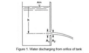
Orifices
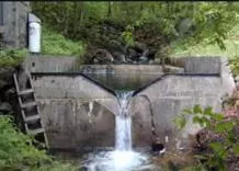
Weirs
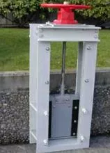
Sluice Gates
Siphons
Outlets for Detention Structures
2
This Week:
Open Channel Flow
Uniform Flow (Manning’s Equation)
Varied Flow
3
Objectives
Students should be able to:
Use Manning’s equation for uniform
flow calculations
Calculate Normal Depth by hand
Calculate Critical Depth by hand
Utilize Flowmaster software for open
channel flow problem-solving
4
Open Channel Flow
Open to the atmosphere
Creek/ditch/gutter/pipe flow
Uniform flow
-EGL/HGL/Channel Slope are
parallel
velocity/depth constant
Varied flow
-EGL/HGL/Channel Slope not
parallel
velocity/depth not constant
5
Uniform Flow in Open Channels
Water depth, flow area, Q and V distribution at
all sections throughout the entire channel reach
remains unchanged
The EGL, HGL and channel bottom lines are
parallel to each other
No acceleration or deceleration
6
Manning’s Equation
Irish Engineer
“On the Flow of Water in Open Channels and
Pipes” (1891)
More:
http://www.engineeringtoolbox.com/mannings-roughness-d_799.html
https://www.hydrologystudio.com/pulp-friction/
https://www.h2ometrics.com/manning-equation/
7
Manning’s Equation-English
Solve for Flow
Q=AV=(
1.486
/n)(A)(R
h
)
2/3
S
1/2
Where:
Q=flow rate (cfs)
A=wetted cross-sectional area (ft
2
)
R
h
=hydraulic radius=A/WP (ft)
WP=wetted perimeter (ft)
S=slope (ft/ft)
n=friction coefficient (dimensionless)
8
Manning’s Equation-Metric
Solve for Flow
Q=AV=(
1
/n)(A)(R
h
)
2/3
S
1/2
Where:
Q=flow rate (cms)
A=wetted cross-sectional area (m
2
)
R
h
=hydraulic radius=A/WP (m)
WP=wetted perimeter (m)
S=slope (m/m)
n=friction coefficient (dimensionless)
9
Manning’s Equation-English
Solve for Velocity
V=(
1.486
/n)(R
h
)
2/3
S
1/2
Where:
V=velocity (ft/sec)
A=wetted cross-sectional area (ft
2
)
R
h
=hydraulic radius=A/WP (ft)
WP=wetted perimeter (ft)
S=slope (ft/ft)
n=friction coefficient (dimensionless)
10
Manning’s Equation-Metric
Solve for Velocity
V=(
1
/n)(R
h
)
2/3
S
1/2
Where:
V=flow rate (meters/sec)
A=wetted cross-sectional area (m
2
)
R
h
=hydraulic radius=A/WP (m)
WP=wetted perimeter (m)
S=slope (m/m)
n=friction coefficient (dimensionless)
11
Manning’s Friction Coefficient
http://www.lmnoeng.com/manningn.htm
Typical values:
Concrete pipe: n=.013
CMP pipe: n=.024
12
Triangular/Trapezoidal
Channels
Must use trigonometry to determine area
and wetted perimeters
13
Pipe Flow
Hydraulic radii and wetted perimeters are
easy to calculate if the pipe is flowing full
or half-full
If pipe flow is at some other depth, then
tables/figures/software are usually used
14
15
Example-Find Q
Find the discharge of a rectangular
channel 5’ wide w/ a 5% grade,
flowing 1’ deep. The channel has a
stone and weed bank (n=.035).
A=5 sf; WP=7’; R
h
=0.714 ft
S=.05
Q=38 cfs
16
Example-Find S
A 3-m wide rectangular irrigation
channel carries a discharge of 25.3
cms @ a uniform depth of 1.2m.
Determine the slope of the channel if
Manning’s n=.022
A=3.6 sm; WP=5.4m; R
h
=0.667m
S=.041=4.1%
17
Friction loss
How would you use Manning’s equation
to estimate friction loss?
18
Using Manning’s equation to
estimate pipe size
Size pipe for Q=39 cfs
Assume full flow
Assume concrete pipe on a 2% grade
Put R
h
and A in terms of Dia.
Solve for D=2.15 ft = 25.8”
Choose a 27” or 30” RCP
Also see Appendix A of your book
Break
19
20
Normal Depth
Given Q, the depth at which the water
flows uniformly
Use Manning’s equation
Must solve by trial/error (depth is in area
term and in hydraulic radius term)
21
Normal Depth Example
Find normal depth in a 10.0-ft wide
concrete rectangular channel having a
slope of 0.015 ft/ft and carrying a flow of
400 cfs.
Assume n=0.013 (concrete)
22
Normal Depth Example
23
Stream Rating Curve
Plot of Q versus depth (or WSE)
Also called stage-discharge curve
24
Specific Energy
Energy above channel bottom
Depth of stream
Velocity head
25
Depth as a function of Specific
Energy
Rectangular channel
Width is 6’
Constant flow of 20 cfs
26
27
28
Critical Depth
Depth at which specific energy is at a
minimum
Other than critical depth, specific energy
can occur at 2 different depths
Subcritical (tranquil) flow d > d
c
Supercritical (rapid) flow d < d
c
29
Critical Velocity
Velocity at critical depth
30
Critical Slope
Slope that causes normal depth to
coincide w/ critical depth
31
Calculating Critical Depth
a
3
/T=Q
2
/g
A=cross-sectional area (sq ft or sq m)
T=top width of channel (ft/m)
Q=flow rate (cfs or cms)
g=gravitational constant (32.2/9.81)
Rectangular Channel—Solve Directly
Other Channel Shape-Solve via trial & error
Critical Depth
(Rectangular Channel)
Width of channel does not vary with depth;
therefore, critical depth (d
c
) can be solved for
directly:
d
c
=(Q
2
/(g*w
2
))
1/3
For all other channel shapes the top width
varies with depth and the critical depth must
be solved via trial and error (or via software
like flowmaster)
32
33
Froude Number
F=Vel/(g*D)
.5
F=Froude #
V=Velocity (fps or m/sec)
D=hydraulic depth=a/T (ft or m)
g=gravitational constant
F=1 (critical flow)
F<1 (subcritical; tranquil flow)
F>1 (supercritical; rapid flow)
34
Varied Flow
Rapidly Varied – depth and velocity change
rapidly over a short distance; can neglect
friction
hydraulic jump
Gradually varied – depth and velocity change
over a long distance; must account for
friction
backwater curves
35
Hydraulic Jump
Occurs when water goes from
supercritical to subcritical flow
Abrupt rise in the surface water
Increase in depth is always from below
the critical depth to above the critical
depth
36
Hydraulic Jump
Velocity and depth before jump (v
1
,y
1
)
Velocity and depth after jump (v
2
,y
2
)
Although not in your book, there are
various equations that relate these
variables. Specific energy lost in the
jump can also be calculated.
37
Hydraulic Jump
http://www.ce.utexas.edu/prof/hodges/classes/Hydraulics.html
http://krcproject.groups.et.byu.net/
http://www.lmnoeng.com/Channels/HydraulicJump.php
Circular hydraulic jumps
http://www-math.mit.edu/~bush/jump.htm
38
Varied Flow
Slope Categories
M-mild slope
S-steep slope
C-critical slope
H-horizontal slope
A-adverse slope
39
Varied Flow
Zone Categories
Zone 1
Actual depth is greater than normal and critical
depth
Zone 2
Actual depth is between normal and critical depth
Zone 3
Actual depth is less than normal and critical depth
40
Water-Surface Profile
Classifications
H2, H3 (no H1)
M1, M2, M3
C1, C3 (no C2)
S1, S2, S3
A2, A3 (no A1)
Water Surface Profiles
http://www.fhwa.dot.gov/engineering/hydraulics/pubs/08090/04.cfm
41
Water Surface Profiles-Change in Slope
http://www.fhwa.dot.gov/engineering/hydraulics/pubs/08090/04.cfm
42
43
Backwater Profiles
Usually by computer methods
HEC-RAS
Direct Step Method
Depth/Velocity known at some section (control
section)
Assume small change in depth
Standard Step Method
Depth and velocity known at control section
Assume a small change in channel length
This review covers hydraulic devices such as orifices, weirs, sluice gates, siphons, and outlets for detention structures. It focuses on open channel flow, including uniform flow and varied flow, and explains how to use Mannings equation for calculations related to water depth, flow area, and velocity distribution. The content delves into the characteristics of uniform flow in open channels and provides information on how to solve for flow and velocity using Mannings equation in both English and Metric units.

Download Presentation

Please find below an Image/Link to download the presentation.
The content on the website is provided AS IS for your information and personal use only. It may not be sold, licensed, or shared on other websites without obtaining consent from the author. Download presentation by click this link. If you encounter any issues during the download, it is possible that the publisher has removed the file from their server.
E N D
Presentation Transcript
CTC 261 Review Hydraulic Devices Orifices Weirs Sluice Gates Siphons Outlets for Detention Structures 1
This Week: Open Channel Flow Uniform Flow (Manning s Equation) Varied Flow 2
Objectives Students should be able to: Use Manning s equation for uniform flow calculations Calculate Normal Depth by hand Calculate Critical Depth by hand Utilize Flowmaster software for open channel flow problem-solving 3
Open Channel Flow Open to the atmosphere Creek/ditch/gutter/pipe flow Uniform flow-EGL/HGL/Channel Slope are parallel velocity/depth constant Varied flow-EGL/HGL/Channel Slope not parallel velocity/depth not constant 4
Uniform Flow in Open Channels Water depth, flow area, Q and V distribution at all sections throughout the entire channel reach remains unchanged The EGL, HGL and channel bottom lines are parallel to each other No acceleration or deceleration 5
Mannings Equation Irish Engineer On the Flow of Water in Open Channels and Pipes (1891) More: http://www.engineeringtoolbox.com/mannings-roughness-d_799.html https://www.hydrologystudio.com/pulp-friction/ https://www.h2ometrics.com/manning-equation/ 6
Mannings Equation-English Solve for Flow Q=AV=(1.486/n)(A)(Rh)2/3S1/2 Where: Q=flow rate (cfs) A=wetted cross-sectional area (ft2) Rh=hydraulic radius=A/WP (ft) WP=wetted perimeter (ft) S=slope (ft/ft) n=friction coefficient (dimensionless) 7
Mannings Equation-Metric Solve for Flow Q=AV=(1/n)(A)(Rh)2/3S1/2 Where: Q=flow rate (cms) A=wetted cross-sectional area (m2) Rh=hydraulic radius=A/WP (m) WP=wetted perimeter (m) S=slope (m/m) n=friction coefficient (dimensionless) 8
Mannings Equation-English Solve for Velocity V=(1.486/n)(Rh)2/3S1/2 Where: V=velocity (ft/sec) A=wetted cross-sectional area (ft2) Rh=hydraulic radius=A/WP (ft) WP=wetted perimeter (ft) S=slope (ft/ft) n=friction coefficient (dimensionless) 9
Mannings Equation-Metric Solve for Velocity V=(1/n)(Rh)2/3S1/2 Where: V=flow rate (meters/sec) A=wetted cross-sectional area (m2) Rh=hydraulic radius=A/WP (m) WP=wetted perimeter (m) S=slope (m/m) n=friction coefficient (dimensionless) 10
Mannings Friction Coefficient http://www.lmnoeng.com/manningn.htm Typical values: Concrete pipe: n=.013 CMP pipe: n=.024 11
Triangular/Trapezoidal Channels Must use trigonometry to determine area and wetted perimeters 12
Pipe Flow Hydraulic radii and wetted perimeters are easy to calculate if the pipe is flowing full or half-full If pipe flow is at some other depth, then tables/figures/software are usually used 13
Example-Find Q Find the discharge of a rectangular channel 5 wide w/ a 5% grade, flowing 1 deep. The channel has a stone and weed bank (n=.035). A=5 sf; WP=7 ; Rh=0.714 ft S=.05 Q=38 cfs 15
Example-Find S A 3-m wide rectangular irrigation channel carries a discharge of 25.3 cms @ a uniform depth of 1.2m. Determine the slope of the channel if Manning s n=.022 A=3.6 sm; WP=5.4m; Rh=0.667m S=.041=4.1% 16
Friction loss How would you use Manning s equation to estimate friction loss? 17
Using Mannings equation to estimate pipe size Size pipe for Q=39 cfs Assume full flow Assume concrete pipe on a 2% grade Put Rh and A in terms of Dia. Solve for D=2.15 ft = 25.8 Choose a 27 or 30 RCP Also see Appendix A of your book 18
Break 19
Normal Depth Given Q, the depth at which the water flows uniformly Use Manning s equation Must solve by trial/error (depth is in area term and in hydraulic radius term) 20
Normal Depth Example Find normal depth in a 10.0-ft wide concrete rectangular channel having a slope of 0.015 ft/ft and carrying a flow of 400 cfs. Assume n=0.013 (concrete) 21
Normal Depth Example Assumed D (ft) 2.00 Area (sqft) 20 Peri. (ft) 14 Rh (ft) 1.43 Rh^.66 Q (cfs) 1.27 356 3.00 30 16 1.88 1.52 640 2.15 21.5 14.3 1.50 1.31 396 22
Stream Rating Curve Plot of Q versus depth (or WSE) Also called stage-discharge curve 23
Specific Energy Energy above channel bottom Depth of stream Velocity head 24
Depth as a function of Specific Energy Rectangular channel Width is 6 Constant flow of 20 cfs 25
Specific Energy Start Depth Depth Increment Flow Rect Channel Width g Critical Depth D+v^2/2g 0.2 ft 0.2 ft 20 cfs 6 ft 32.2 ft/sec^2 0.70 ft Depth 0.20 0.40 0.60 0.80 1.00 1.20 1.40 1.60 1.80 2.00 2.20 2.40 2.60 2.80 3.00 Area 1.20 2.40 3.60 4.80 6.00 7.20 8.40 9.60 10.80 12.00 13.20 14.40 15.60 16.80 18.00 Velocity 16.67 8.33 5.56 4.17 3.33 2.78 2.38 2.08 1.85 1.67 1.52 1.39 1.28 1.19 1.11 Specific Energy 4.51 1.48 1.08 1.07 1.17 1.32 1.49 1.67 1.85 2.04 2.24 2.43 2.63 2.82 3.02 26
Specific Energy Curve 3.5 3.0 Channel Depth (ft) 2.5 2.0 1.5 1.0 0.5 0.0 0.0 1.0 2.0 3.0 4.0 5.0 Specific Energy (ft) 27
Critical Depth Depth at which specific energy is at a minimum Other than critical depth, specific energy can occur at 2 different depths Subcritical (tranquil) flow d > dc Supercritical (rapid) flow d < dc 28
Critical Velocity Velocity at critical depth 29
Critical Slope Slope that causes normal depth to coincide w/ critical depth 30
Calculating Critical Depth a3/T=Q2/g A=cross-sectional area (sq ft or sq m) T=top width of channel (ft/m) Q=flow rate (cfs or cms) g=gravitational constant (32.2/9.81) Rectangular Channel Solve Directly Other Channel Shape-Solve via trial & error 31
Critical Depth (Rectangular Channel) Width of channel does not vary with depth; therefore, critical depth (dc) can be solved for directly: dc=(Q2/(g*w2))1/3 For all other channel shapes the top width varies with depth and the critical depth must be solved via trial and error (or via software like flowmaster) 32
Froude Number F=Vel/(g*D).5 F=Froude # V=Velocity (fps or m/sec) D=hydraulic depth=a/T (ft or m) g=gravitational constant F=1 (critical flow) F<1 (subcritical; tranquil flow) F>1 (supercritical; rapid flow) 33
Varied Flow Rapidly Varied depth and velocity change rapidly over a short distance; can neglect friction hydraulic jump Gradually varied depth and velocity change over a long distance; must account for friction backwater curves 34
Hydraulic Jump Occurs when water goes from supercritical to subcritical flow Abrupt rise in the surface water Increase in depth is always from below the critical depth to above the critical depth 35
Hydraulic Jump Velocity and depth before jump (v1,y1) Velocity and depth after jump (v2,y2) Although not in your book, there are various equations that relate these variables. Specific energy lost in the jump can also be calculated. 36
Hydraulic Jump http://www.ce.utexas.edu/prof/hodges/classes/Hydraulics.html http://krcproject.groups.et.byu.net/ http://www.lmnoeng.com/Channels/HydraulicJump.php Circular hydraulic jumps http://www-math.mit.edu/~bush/jump.htm 37
Varied Flow Slope Categories M-mild slope S-steep slope C-critical slope H-horizontal slope A-adverse slope 38
Varied Flow Zone Categories Zone 1 Actual depth is greater than normal and critical depth Zone 2 Actual depth is between normal and critical depth Zone 3 Actual depth is less than normal and critical depth 39
Water-Surface Profile Classifications H2, H3 (no H1) M1, M2, M3 C1, C3 (no C2) S1, S2, S3 A2, A3 (no A1) 40
Water Surface Profiles http://www.fhwa.dot.gov/engineering/hydraulics/pubs/08090/04.cfm 41
Water Surface Profiles-Change in Slope http://www.fhwa.dot.gov/engineering/hydraulics/pubs/08090/04.cfm 42
Backwater Profiles Usually by computer methods HEC-RAS Direct Step Method Depth/Velocity known at some section (control section) Assume small change in depth Standard Step Method Depth and velocity known at control section Assume a small change in channel length 43