Understanding Fanno and Rayleigh Lines in Adiabatic Flow
Fanno and Rayleigh lines on the h-s diagram help in analyzing adiabatic flow with friction effects. The Fanno line represents frictional flow, while the Rayleigh line signifies non-adiabatic, frictionless flow. These lines aid in plotting flow properties and understanding phenomena like shock waves and nozzle behavior in compressible flow. By examining intersections of these lines, one can describe flow conditions before and after a normal shock wave. This summary delves into the characteristics and applications of Fanno and Rayleigh lines in fluid dynamics.

Download Presentation

Please find below an Image/Link to download the presentation.
The content on the website is provided AS IS for your information and personal use only. It may not be sold, licensed, or shared on other websites without obtaining consent from the author. Download presentation by click this link. If you encounter any issues during the download, it is possible that the publisher has removed the file from their server.
E N D
Presentation Transcript
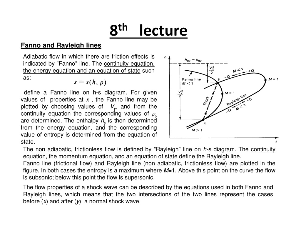
8thlecture Fanno and Rayleigh lines Adiabatic flow in which there are friction effects is indicated by "Fanno" line. The continuity equation, the energy equation and an equation of state such as: define a Fanno line on h-s diagram. For given values of properties at x , the Fanno line may be plotted by choosing values of continuity equation the corresponding values of y are determined. The enthalpy hyis then determined from the energy equation, and the corresponding value of entropy is determined from the equation of state. The non adiabatic, frictionless flow is defined by "Rayleigh" line on h-s diagram. The continuity equation, the momentum equation, and an equation of state define the Rayleigh line. Fanno line (frictional flow) and Rayleigh line (non adiabatic, frictionless flow) are plotted in the figure. In both cases the entropy is a maximum where M=1. Above this point on the curve the flow is subsonic; below this point the flow is supersonic. The flow properties of a shock wave can be described by the equations used in both Fanno and Rayleigh lines, which means that the two intersections of the two lines represent the cases before (x) and after (y) a normal shock wave. Vy, and from the
Normal shock in a convergent divergent nozzle Isentropic flow occurs in a convergent-divergent nozzle if the nozzle design pressure at the exit plane is equal to back pressure. As shown in the figure, a range of back pressures between p2and p4a stationary normal shock appears in the divergent portion of the nozzle. The flow behaves isentropically till a point, where a sudden transition from supersonic speed to subsonic speed occurs. Beyond the shock isentropically at subsonic speed and decelerates so that at the exit the pressure will equal the back pressure. The location of shock depends on the back pressure. As shown in the figure, if the back pressure is equal to p4, the shock appears right at the exit plane. If the back pressure is less than p4, the flow remains unchanged and adjustment to back pressure occur outside the nozzle. With back pressures between p4and p6, the nozzle out- flow is supersonic and the nozzle is said to be over- expanded. A succession of two-dimensional oblique shocks and expansion waves appear outside the nozzle. When the backpressure equals the design pressure, the shock disappears an the flow is isentropic. When the back pressure is less than p6, the nozzle is underexpand and expansion and compression waves occrs outside the nozzle. When the back pressure is larger than p2, the flow through the nozzle will be entirly subsonic and the mass flow rate will depend on the back pressure. When the velocity in the throat reaches sonic speed, the mass rate of flow is constant for all nack pressure below p2. the flow proceeds
The last figure shows how the exit pressure varies with the back pressure. When the flow is subsonic at the exit, the exit pressure is equal to the back pressure. When the nozzle is overexpanded, the exit pressure is less than the back pressure; when the nozzle is underexpanded, the exit pressure is greater than the back pressure. In a perfectly expanded nozzle, which is either a converging or a shock-free converging-diverging nozzle, the exit pressure is exactly equal to the back pressure. Supersonic diffusers
Two difficulty are possible. In one solution, illustrated in the figure in the last slide, the Mach number is increased by accelerating the flow to the design causing the shock to move toward the lip of the diffuser. Since the throat area is less than Ay, the mass flow is still reduced. An increase in the Mach number to a value beyond the design Mach number locates the shock at the lip of the diffuser. The resulting subsonic flow downstream of the shock then accelerates to sonic flow at the throat. Tis state is indicated by point b in the adjacent figure. Upon further increase of the Mach number swallowed by the diffuser and appears downstream of the throat. methods of circumventing this Mach number, the shock is
, t The Mach number is then decelerated to the design Mach number, Md, and the shock reaches an equilibrium position at the throat where M=1. At this location the shock is of vanishing strength and there is no loss in stagnation pressure. But at this design condition the diffuser is unstable and a slight decrease in the Mach number causes the shock to move upstream out of the diffuser, which is undesirable. For this reason the shock is usually located slightly downstream of the throat. Another method of eliminating the shock in supersonic diffuser is to use a variable-area diffuser as shown in the given figure. By increasing the throat area the mass flow increased, causing the shock to move toward the diffuser inlet. A further increase in the throat area to state c (in the figure in the last slide) locates the shock at the lip of the diffuser. When the throat area exceeds, , the shock is swallowed, appearing instead at an equilibrium position downstream of the throat. The throat area can then be decelerated until the design conditions are attained.
At low supersonic speeds, start-up difficulties can be reduced by eliminating the convergent potion of the diffuser. A shock wave forms at the diffuser's entrance, so that the fluid enters the diffuser at subsonic speed, then traveling at slower speeds as the cross-sectional area of the diffuser increases. Since the loss of stagnation pressure varies directly with the strength of the shock, this design approach is recommended only for low Mach numbers where the loss is small. At high Mach numbers, a series of oblique shock waves appear in the fluid as it flows past a spike located in the diffuser. Supersonic wind tunnels Tests are conducted in supersonic wind tunnel to simulate the supersonic flow encountered in actual flight. The gas must flow across the test section at the specified Mach number and the flow must be shock free and uniform. The figure shows an ideal supersonic wind tunnel. Air at stagnation conditions Toand po1is first accelerated through convergent-divergent nozzle. flows at supersonic frictionless constant-area test section. an isentropic The through a air then speed a Finally, the air flows isentropically through a convergent-divergent diffuser, where it recovers its fluid pressure. In practice, there are friction losses in stagnation pressure. Compensation for this loss in stagnation pressure is accomplished by power input to the system. To minimize the power required by the compressor, the air is cooled in heat exchanger befor entering the compressor