Troubleshooting CM02 Cold Gate Valves at Fermilab

Issues have arisen with the CM02 cold gate valves at Fermilab, affecting the operation and reliability of the valves. Problems include leakage, improper sealing, and unexpected pressure differentials during installation, leading to the introduction of gases into the cavity string. Detailed descriptions of the upstream and downstream valves, as well as leak check results and configuration diagrams, provide insights into the challenges faced during leak checks and installations.

Download Presentation

Please find below an Image/Link to download the presentation.
The content on the website is provided AS IS for your information and personal use only. It may not be sold, licensed, or shared on other websites without obtaining consent from the author. Download presentation by click this link. If you encounter any issues during the download, it is possible that the publisher has removed the file from their server.
E N D
Presentation Transcript
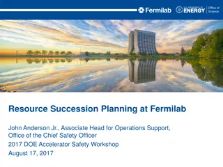
Fermilab F1.3-2 (CM02) Beam Valves Jerry Leibfritz and Tug Arkan
Issues with Cold Gate Valves Both CM02 cold gate valves do not operate properly - each exhibit different characteristics - highly suspect they leak through and/or don t seal properly As a result - Experienced unexpected pressure differentials in various configurations during leak check and installation of CM02 at WS5 and at CMTS, resulting in filtered boiled-off nitrogen gas and cleanroom air being introduced into the cavity string in an uncontrolled manner. 2
Upstream Cold Gate Valve Downstream (Endcap) Upstream (Feedcap) Open Closed MFC MFC Configuration During WS5 Leak Check Upstream Gate Valve (#472XX-XEOX-ALA1/0066) - excessively rough to operate - verified valve was fully closed - able to see vacuum changes through closed valve in configuration shown above, suspected to be leaking through. Not trivial to calculate a reliable leak rate. 3
Downstream Cold Gate Valve Downstream (Endcap) Upstream (Feedcap) Closed Open Closed MFC PS Spool Configuration During CMTS Installation Downstream Gate Valve (#472XX-XEOX-ALA1/0015) - excessively easy to operate/turn - leaked through when expected to be closed in configuration shown above. Not trivial to calculate a reliable leak rate. - valve is very touchy and cannot be relied on to seal properly 4
Additional Information In all leak checks of full cavity string system, no outside air leaks were detected Upstream and downstream right-angle valves (RAV) were leak checked successfully (not leaking through) Cavity string experienced pressure changes at uncontrolled rates though CMTS test did not show any excessive FE for this CM: - F1.3-02: One cavity FE onset 12.5 MV/m; 7 acceptable 5
F1.3-02 (CM02) Current Configuration Diagram Cavity String Cryostat Vessel Upstream (Feedcap) Downstream (Endcap) Short spool with a mini right angle valve (RAV) (closed) Flange adapter with a right angle valve (RAV) (closed) Cold GV (closed) Cold GV (closed) 6
Path forward 1. Ignore 2. Dale Gill, vacuum engineer at SLAC requested better assessment of the leak rate for these CGVs: Work on CGV and try to assess a better leak rate, this will require opening, closing CGV, pushing through nitrogen or helium through the closed CGVs and disturbing the current vacuum integrity of CM02 beamline Risky for the beamline integrity of the tested and qualified CM 3. Special handling/installation scheme at SLAC: next slide 7
Proposed scheme for CM installation at SLAC F1.3-2 aka CM02 has leaking through gate valves (E-7 mbar x liter / second range) at both UP an DS ends of the CM. (JLab CM02 might have the same issue) Currently we have Faraday cup manifold (F10040886) assembled to US gate valve (closed) and F10023441 assembled to DS gate valve (closed). ` Fermilab proposes to ship F1.3-2 beamline as- is (under vacuum) with its current end configuration. (will require some additional pumping configurations during final QC after BLA installation One proposed procedure F1.3-2 CM(n-1) CM(n) CM(n+1) 1. Move F1.3-2 to the tunnel & backfill to atmosphere 2. Ensure both gate valves are closed 3. Install BLA between F1.3-2 and CM(n-1) and CM(n+1) 4. Pump & Leak check from each side of F1.3-2 at the same time F10040886 8
 Beam")


 Current Configuration Diagram")