Safety Guidelines for Hyperbaric Pressure Release Valve Installations
Hyperbaric compressed air systems require Pressure Release Valves (PRV) to ensure safety in case of automatic regulating valve failure. This bulletin explains the critical need for PRVs, their working principle, and the importance of proper installation. It also details the setup of compressor stations and the role of pressure relief valves in protecting against over-pressurization. Understanding these safety measures is crucial for maintaining the integrity of hyperbaric installations.

Download Presentation

Please find below an Image/Link to download the presentation.
The content on the website is provided AS IS for your information and personal use only. It may not be sold, licensed, or shared on other websites without obtaining consent from the author. Download presentation by click this link. If you encounter any issues during the download, it is possible that the publisher has removed the file from their server.
E N D
Presentation Transcript
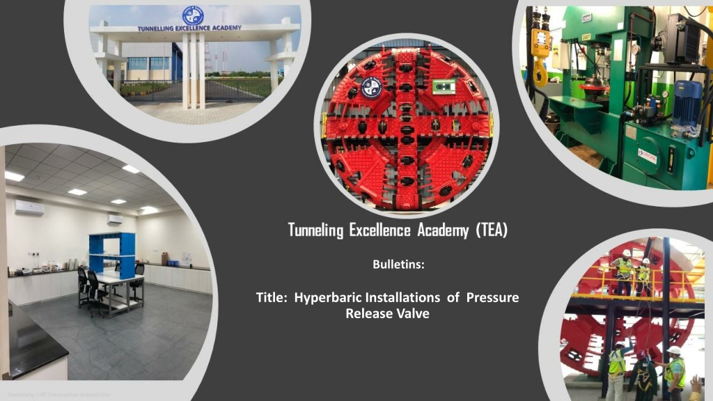
Bulletins: Title: Hyperbaric Installations of Pressure Release Valve Sensitivity: LNT Construction Internal Use
Hyperbaric Installations of Pressure Release Valve Hyperbaric compressed air system set ups are covered by many regulations (not covered in this bulletin) however they all require Pressure Release Valves (PRV) to be installed in case of failure to the automatic regulating valves (commonly known as Samson Valves). If failure of this valve occurs then protection to the system is critical from the PRV, and the PRV must be able to release air flow marginally above the working pressure (in this example shown as 1.5bar), without increasing the set 1.5 bar face pressure, by venting off the air flow volume generated form the installed compressors. The following schematic and narrative will explain this critical safe system of work requirement Sensitivity: LNT Construction Internal Use
Compressor Station Control Room (surface) Schematic compressed air system Excavation Chamber Diesel Stand By 9 Bar Duty 9 Bar Elect Assist 9 Bar Elect Man- lock 6m Storge Tank Oil Mist Filter Pressure Reducing valve (9 to 3.5bar) HP Air Line to Locks 3.5 Bar TBM Twin e.g: 1.5bar 3? Stora ge Tank 9 bar 21 C Pressure Reducing Valve (PRV) Tunnel Samson pressure Control station Oil Mist Filter Chiller Plant CHD Pressure Monitoring Line in this e.g 1.5 bar minimum Samson Control Unit Duty Samson Control Unit Stand by Non Return valve/One Way Valve Manual Setting Pressure Realise valve. Manual setting to actual CH Working pressure On Day Operation. (PRV-1) in this example would be set to release at just over 1.2 bar Pre Set Pressure Realise Valve. Pre-Set Maximum Expected Working Pressure. (PRV-2) Sensitivity: LNT Construction Internal Use
Pressure Relief Valve Pressure Relief Valve Working Principle The pressure relief valves are used to protect the cutter head intervention persons potential excessive pressure, due to any failure of the system. Its primary function is to limit the system pressure within a specified range. It is normally a closed type and it opens when the pressure exceeds a specified maximum value by diverting pump flow back to the exhaust line. The simplest type valve contains a poppet held in a seat against the spring force as shown in above figure. This type of valves has two ports; one of which is connected to the Cutter Head chamber line and another is exhaust line . When the system pressure exceeds the pre-set value, the poppet lifts and the air is escaped through the exhaust line directly. It reduces the system pressure and as the pressure reduces to the set limit again the valve From Sensitivity: LNT Construction Internal Use closes.
Single High Lift Safety Relief Valve Pressure release valves are fitted to alleviate over pressurisation of the working chamber. The pressure release valves duty output must match the output flow of all compressors that are designated to be used, including standby. All hyperbaric systems require as absolute min requirement; three number in-line 17m3/min (600cfm) compressors (Duty, Assist & Standby) with total airflow of 3x17 = 51m3/min (1800cfm) capacity. The anticipated actual flow rate depends upon geology and area of tbm face to be encountered, noting detail design may require more compressors to be used in the works. More air flow will require fitting of higher capacity release valves or several in-line type. Dependent upon the compressor type used, the pressure could be expected up to 9 bar. The pressure at the rear of the TBM should be reduced from 9 bar down to 0.5 bar above the anticipated maximum working pressure (in this example set at 3.5 bar). The correct valve to choose is the one with duty of min 3.5 bar in this case the 4.0 bar is closest. Also note the blow off pressure at 0.5 bar is 51.8m3/min for the DN100 valve. In this example, the CHD working pressure will be required at 1.5 bar, therefore the person in charge of hyperbaric working will set the manual PRV to blow off at circa 1.5 bar (set this valve once the head pressure is stabilised and before persons enter the CHD). As can be seen from the valve duty chart up to 92.7m3/min can be vented off at 1.5bar. Noting the compressor configuration in the example is circa 51m3/min. therefore correct vale specified and Safe System of Work in place. Sensitivity: LNT Construction Internal Use
END Sensitivity: LNT Construction Internal Use