Evolution of RCS Design and Upgrade Process at Fermilab
The Fermilab accelerators have undergone significant upgrades over the years, with developments such as the 2 GeV Linac, RCS design improvements, and the Snowmass 2.4 MW upgrade with RCS. Key advancements include enhanced beam intensity, better orbit control, and reliability. Various parameter variations have been considered for RCS design optimization. Technical knowledge and capabilities have enabled the construction of a new RCS with significantly improved performance compared to the previous Fermilab Booster.

Download Presentation

Please find below an Image/Link to download the presentation.
The content on the website is provided AS IS for your information and personal use only. It may not be sold, licensed, or shared on other websites without obtaining consent from the author. Download presentation by click this link. If you encounter any issues during the download, it is possible that the publisher has removed the file from their server.
E N D
Presentation Transcript
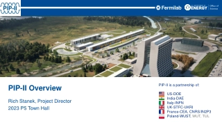
2 GeV Linac + RCS ACE Configuration Jeffrey Eldred, special thanks to Sergei Nagaitsev, Valeri Lebedev ACE Science Workshop June 15, 2023
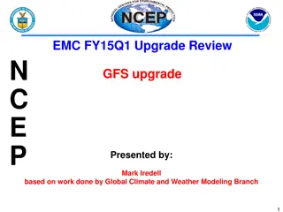
2 Upgrade Design History & Process In 2003, Proton Driver Study II (PD2): 0.6 GeV Linac, New 0.6-8 GeV RCS In 2010, Project X ICD-2: 2 GeV Linac, New 2-8 GeV RCS. In 2018, S. Nagaitsev and V. Lebedev: updated version of ICD-2. In 2019, J. Eldred, V. Lebedev, A. Valishev: parametric study of RCS design. In 2021, Committee for Fermilab Booster Upgrade an integrated design effort: Science Working Group chaired by R. Harnik Physics Opportunities for the Fermilab Booster Replacement Accelerator Working Group chaired by M. Syphers An Upgrade Path for the Fermilab Accelerator Complex In 2022, ACE Central Design Group Accelerators Bottom Line: Technical considerations are well understood at this point. We know how to build a new RCS with beam intensity four times greater intensity than the Fermilab Booster. 2 9/26/2024 Jeffrey Eldred |Snowmass 2.4 MW Upgrade with RCS
3 RCS Design vs Booster Design 1. RCS lattice design avoids transition-crossing. 2. RCS injection accommodates a higher injection energy. 3. RCS features a larger aperture and better orbit control. 4. RCS has beampipes inside dipoles, avoid impedance from laminations. 5. RCS has more shielding from surface and a wider tunnel. 6. RCS has new components with greater reliability, precision, controls. 7. RCS has better designed injection straight with downstream collimators. There are many different parameter variations we can consider for the RCS design, but the basic argument for performance is quite straightforward. 3 9/26/2024 Jeffrey Eldred |Snowmass 2.4 MW Upgrade with RCS
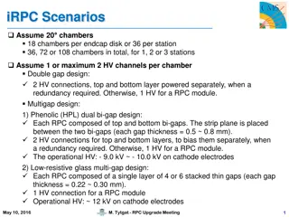
4 Some Parameter Variations We Considered - Harmonic RF for suppression of space-charge at injection. - Correlated instead of anti-correlated injection painting. - Using an asymmetric injection chicane to save space. - Larger transverse emittance, higher/lower injection energy. - Highly periodic RCS (4-8 superperiods) vs racetrack RCS (2 superperiods) - Use of nonlinear integrable optics or electron lenses - Slip-stacking beams as much higher than PIP-II intensity. - Use/avoidance/upgrade of Fermilab Recycler - RCS extraction at greater than 8 GeV. But I won t go into detail on these topics today. 4 9/26/2024 Jeffrey Eldred |Snowmass 2.4 MW Upgrade with RCS
5 Updated ICD-2 used as baseline RCS scenario In 2003, Proton Driver Study II (PD2): 0.6 GeV Linac, New 0.6-8 GeV RCS In 2010, Project X ICD-2: 2 GeV Linac, New 2-8 GeV RCS. In 2018, S. Nagaitsev and V. Lebedev: updated version of ICD-2. In 2019, J. Eldred, V. Lebedev, A. Valishev: parametric study of RCS design. In 2021, Committee for Fermilab Booster Upgrade an integrated design effort: Science Working Group chaired by R. Harnik Physics Opportunities for the Fermilab Booster Replacement Accelerator Working Group chaired by M. Syphers An Upgrade Path for the Fermilab Accelerator Complex In 2022, ACE Central Design Group Accelerator Working Group Bottom Line: Technical considerations are well understood at this point. We know how to build a new RCS with beam intensity four times greater intensity than the Fermilab Booster. 5 9/26/2024 Jeffrey Eldred |Snowmass 2.4 MW Upgrade with RCS
6 ACE RCS Configurations ACS RCS v1: 10Hz RCS ACS RCS v2: 20Hz RCS + 2GeV AR to facilitate injection. ACS RCS v3: 20Hz RCS + Current upgrade to 5mA Assume all scenarios inject 6x25e12 particles into the Recycler at 8 GeV. Used ICD-2 / Nagaitsev-Lebedev ring as baseline for 10Hz RCS. For 20Hz considered ceramic rather than metallic beampipe, greater RF and magnet power supplies, more challenging to flatten injection. 6 9/26/2024 Jeffrey Eldred |Snowmass 2.4 MW Upgrade with RCS
7 7 Updated ICD-2 10 Hz RCS Configuration 7 9/26/2024 Jeffrey Eldred |Snowmass 2.4 MW Upgrade with RCS
8 High-level Parameters 8 9/26/2024 Jeffrey Eldred |Snowmass 2.4 MW Upgrade with RCS
9 Racetrack Architecture Long dispersion-free straights sections for injection, collimation, RF, extraction.. Simple FODO bending arcs with small max betas (16m) and small max dispersion (0.6m). 9 9/26/2024 Jeffrey Eldred |Snowmass 2.4 MW Upgrade with RCS
10 Dipole and Quad Magnet Designs 17.4 T/m 0.87 T 2D calculations of conductor currents, field uniformity, saturation effects. Similar calculations made for corrector magnets. 10 9/26/2024 Jeffrey Eldred |Snowmass 2.4 MW Upgrade with RCS
11 Dipole and Quad Magnet Designs 11 9/26/2024 Jeffrey Eldred |Snowmass 2.4 MW Upgrade with RCS
12 Injection / Collimation Collimators Injection Foil Collimation region downstream of injection foil to collect particles scattering off the injection foil before the first bending arc. Adequate phase-advance to get good collimation efficiency. 12 9/26/2024 Jeffrey Eldred |Snowmass 2.4 MW Upgrade with RCS
13 Injection Painting Anti-Correlated Injection Painting Near-KV Injected Distribution Peak foil hit density of 22 hits / mm2 per inj. particle 13 9/26/2024 Jeffrey Eldred |Snowmass 2.4 MW Upgrade with RCS
14 Collimators MARS Calculations 14 9/26/2024 Jeffrey Eldred |Snowmass 2.4 MW Upgrade with RCS
15 Extraction Trajectory 15 9/26/2024 Jeffrey Eldred |Snowmass 2.4 MW Upgrade with RCS
16 RF Cavities Perpendicular-bias quarter-wave RF cavity design. Additional details about cavity design and RF modulators etc in ICD-2 report. 16 9/26/2024 Jeffrey Eldred |Snowmass 2.4 MW Upgrade with RCS
Boosters and RCSs at present (examples) CERN PS Booster 1 Hz rate (non-resonant) Metallic vacuum chamber Fermilab Booster 15 Hz (resonant) No vacuum chamber (this is what we are trying to correct) J-PARC RCS 25 Hz (resonant) Ceramic vacuum chamber The transition from ceramic to metallic (and from resonant to non-resonant) occurs at about 15 Hz S. Nagaitsev | RCS concept 7/20/2022
18 18 10Hz vs. 20Hz Eddy Current Heating Effects 18 9/26/2024 Jeffrey Eldred |Snowmass 2.4 MW Upgrade with RCS
Vacuum chamber The competing effects are: shielding and distortion of the dipole bend field by eddy currents, excited in the vacuum chamber; vacuum chamber mechanical integrity under the atmospheric pressure; vacuum chamber heating by eddy currents; transverse beam impedance due to the wall resistivity; geometric ring acceptance. Eddy current heating (per unit length) d a dP dz c 3 2 R w w ramp = 2 B AC 2 Field distortions (time-dependent): Require corrections during ramping S. Nagaitsev | RCS concept 7/20/2022
Ceramic vacuum chambers at J-PARC From: M. Kinsho (JAEA), 2005 S. Nagaitsev | RCS concept 7/20/2022
21 Implications of Ceramic Beampipe J-PARC provides a clear precedent that ceramic vacuum ducts can be constructed and performance well in an accelerator environment. However we would need to do this for different parameters, and relying on different vendors. Not R&D exactly, but certainly development. - Although R&D could improve the design or manufacturing. J-PARC uses a 170mm aperture whereas that 10 Hz RCS uses a 44mm aperture. Will the 20 Hz RCS need a large aperture to avoid resistive wall instability? For our 20 Hz cost analysis we used 100mm aperture. - On the other hand, if we can manage the impedance effect and take advantage of that larger aperture a x5 overdesign! - This is the main cost-driver for 20Hz vs 10Hz in our analysis. 21 9/26/2024 Jeffrey Eldred |Snowmass 2.4 MW Upgrade with RCS
22 22 Flat Injection for a 20Hz-Resonant RCS 22 9/26/2024 Jeffrey Eldred |Snowmass 2.4 MW Upgrade with RCS
23 Flat Injection for 20Hz-Resonant RCS To inject 25e12 with 2mA current, takes 2ms. For a 20 Hz sinusoidal ramp between 2 GeV and 8 GeV, the beam momentum changes 3.3% over 2ms. For 0.6m dispersion, this is 20mm of orbit movement that has to be compensated carefully. At 5mA its only 0.8mm of orbit movement. Using an AR also solves this problem. Maybe we can compensate without current upgrade or AR, but we ll see it also helps with a foil. Don t want to build an RCS starting with bottleneck. 23 9/26/2024 Jeffrey Eldred |Snowmass 2.4 MW Upgrade with RCS
24 24 Foil-Injection Considerations 24 9/26/2024 Jeffrey Eldred |Snowmass 2.4 MW Upgrade with RCS
25 Updated ICD-2 used as baseline RCS scenario In 2003, Proton Driver Study II (PD2): 0.6 GeV Linac, New 0.6-8 GeV RCS In 2010, Project X ICD-2: 2 GeV Linac, New 2-8 GeV RCS. In 2018, S. Nagaitsev and V. Lebedev: updated version of ICD-2. In 2019, J. Eldred, V. Lebedev, A. Valishev: parametric study of RCS design. In 2021, Committee for Fermilab Booster Upgrade an integrated design effort: Science Working Group chaired by R. Harnik Physics Opportunities for the Fermilab Booster Replacement Accelerator Working Group chaired by M. Syphers An Upgrade Path for the Fermilab Accelerator Complex In 2022, ACE Central Design Group Accelerator Working Group Bottom Line: Technical considerations are well understood at this point. We know how to build a new RCS with beam intensity four times greater intensity than the Fermilab Booster. 25 9/26/2024 Jeffrey Eldred |Snowmass 2.4 MW Upgrade with RCS
26 Foil-Heating effects, for 33e12 every 20 Hz Scenario 1: Upgrade PIP-II linac to 5mA pulsed. Scenario 2: Use six 120 Hz painting cycles to accumulate beam in 2- GeV AR every 20 Hz. 26 9/26/2024 Jeffrey Eldred |Snowmass 2.4 MW Upgrade with RCS
27 Generous 17m Injection Straight for 2-GeV H- H- Foil Stripping Injection 17 m straight. 27 9/26/2024 Jeffrey Eldred |Snowmass 2.4 MW Upgrade with RCS
28 28 RCS for MuC Proton Driver 28 9/26/2024 Jeffrey Eldred |Snowmass 2.4 MW Upgrade with RCS
29 How to get from ACE RCS to MuC PD? Consider ACE RCS that provides 37e12 at 8 GeV every 20Hz = 950 kW. What can I change at that point? - I can change the injection energy / intensity (maybe). - I can change the extraction energy (maybe) or reaccelerate. - I can t easily change the aperture. - I definitely can t change the circumference. The best ACE RCS to MuC PD scenario would be to design for a subsequent upgrade or overdesign, for a MuC proton driver later. - Using similar designs/costs to what I presented already, consider an RCS that provides 100e12 at 12 GeV every 10 Hz for 2MW - Then add a bunch compressor ring and combiner line. 29 9/26/2024 Jeffrey Eldred |Snowmass 2.4 MW Upgrade with RCS
30 Idea: Fast-Ramping HTS Proton RCS Recall that the muon collider design already requires fast-ramping HTS magnets for the muon RCS accelerator. - Could similar technology be applied to proton RCS? The parameters are a little different, proton RCS application needs: aperture (5-20 cm), dipole field (1-4 T), ramping (60-600 T/s) Larger aperture at same circumference and extraction energy -> greater line density, better field uniformity. Shorter circumference at same extraction energy and aperture -> greater line density, more efficient RF acceleration. Greater energy at same circumference and aperture. -> more beam power at intensity. Consider 250m RCS, 12 GeV, 10 Hz, 2x100e12 = 4 MW. 30 9/26/2024 Jeffrey Eldred |Snowmass 2.4 MW Upgrade with RCS
31 Idea: Fast-Ramping HTS Proton RCS YBCO-based HTS super-ferric dipole demonstrated >300 T/s. paper. Still some ways to go to desired proton RCS parameters. 31 9/26/2024 Jeffrey Eldred |Snowmass 2.4 MW Upgrade with RCS
Three Questions Slide 1.How will your system/development address the BR goals of DUNE/LBNF, New Physics, MuC? DUNE/LBNF: 10Hz RCS may be the lowest cost, lowest risk configuration. New Physics: Spigots yesterday, CW up to 2 GeV MuC: There s a viable path, but advantage goes to Linac option. RCS gets more interesting with higher energies. 2. What are the biggest technical/performance risks of your system/development? H- Foil Injection, Laser stripping R&D. Looks okay, but biggest risk/limit. Ceramic/Dielectric Beampipe. Barrier to 20+ Hz ramp rate. MuC R&D, proton compression, HTS, muon production, cooling. 3. What are the most sensible first steps to enable progress in your system/ development? What can be done before the next ACE event (Fall 23 workshop)? Start prototype RCS ceramic beampipes. Create decision tree/timeline for choosing RCS vs Linac upgrade. Resolve MuC R&D plan, role for Fermilab proton complex. 32 9/26/2024 Jeffrey Eldred |Snowmass 2.4 MW Upgrade with RCS


")