Classification of Control Valves in Hydraulic Systems
Control valves in hydraulic systems are classified based on the number of ways for switching positions and actuation mechanisms. Types include three-position four-way valves for double-acting cylinders and two-position four-way valves for faster operation. Actuation mechanisms range from manual and mechanical to solenoid, hydraulic, and pneumatic, each serving specific purposes in controlling fluid flow in hydraulic circuits.

Download Presentation

Please find below an Image/Link to download the presentation.
The content on the website is provided AS IS for your information and personal use only. It may not be sold, licensed, or shared on other websites without obtaining consent from the author. Download presentation by click this link. If you encounter any issues during the download, it is possible that the publisher has removed the file from their server.
E N D
Presentation Transcript
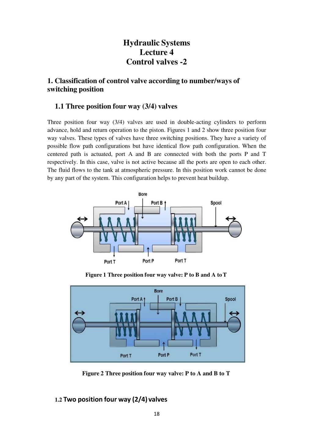
HydraulicSystems Lecture 4 Control valves -2 1. Classification of control valve according to number/ways of switching position 1.1 Three position four way (3/4) valves Three position four way (3/4) valves are used in double-acting cylinders to perform advance, hold and return operation to the piston. Figures 1 and 2 show three position four way valves. These types of valves have three switching positions. They have a variety of possible flow path configurations but have identical flow path configuration. When the centered path is actuated, port A and B are connected with both the ports P and T respectively. In this case, valve is not active because all the ports are open to each other. The fluid flows to the tank at atmospheric pressure. In this position work cannot be done by any part of the system. This configuration helps to prevent heat buildup. Figure 1 Three position four way valve: P to B and A toT Figure 2 Three position four way valve: P to A and B to T 1.2 Two position four way (2/4)valves 18
The two position four way valves have only two switching positions and do not have any mid position. Therefore, they are also known as impulse valves. The typical connections of 2/4 valves is shown in Figures.7 and.8. These valves can be used to operate double acting cylinders. These are also used to reciprocate or hold an actuator. The operation is faster because the distance between ports of these valves is smaller. Hence, these valves are used on machines where fast reciprocation cycles are needed such as punching and stamping etc. 2. Classification based on actuation mechanism 1. Manual actuation In this type, the spool is operated manually. Manual actuators are hand lever, push button and pedals etc. 2. Mechanical actuation The DCV spool can be operated by using mechanical elements such as roller and cam, roller and plunger and rack and pinion etc. In these arrangements, the spool end is of roller or a pinion gear type. The plunger or cam or rack gear is attached to the actuator. Thus, the mechanical elements gain some motion relative to the actuator (cylinder piston) which can be used for the actuation. 3. Solenoidactuation The solenoid actuation is also known as electrical actuation. The schematic of solenoid actuation is shown in Figure.9. The energized solenoid coil creates a magnetic force which pulls the armature into the coil. This movement of armature controls the spool position. The main advantage of solenoid actuation is its less switchingtime. 4. Hydraulic actuation This type actuation is usually known as pilot-actuated valve and a schematic is shown in Figure 10. In this type of actuation, the hydraulic pressure is directly applied on the spool. The pilot port is located on one end of the valve. Fluid entering from pilot port operates against the piston and forces the spool to move forward. The needle valve is used to control the speed of the actuation. 5. Pneumatic actuation DCV can also be operated by applying compressed air against a piston at either end of the valve spool. The construction of the system is similar to the hydraulic actuation as shown in Figure 10. The only difference would be the actuation medium. The actuation medium is the compressed air in pneumatic actuation system. 6. Indirect actuation of directional control valve The direction control valve can be operated by manual, mechanical, solenoidal (electrical), hydraulic (pilot) and pneumatic actuations. The mode of actuation does not have any influence on the basic operation of the hydraulic circuits. Mostly, the direct 19
actuation is restricted to use with smaller valves only because usually lot of force is not available. The availability of limited force is the greatest disadvantage of the direct actuation systems. In practice, the force required to shift the spool is quiet higher. Therefore, the larger valves are often indirectly actuated in sequence. First, the smaller valve is actuated directly and the flow from the smaller valve is directed to either side of the larger valve. The control fluid can be supplied by the same circuit or by a separate circuit. The pilot valve pressure is usually supplied internally. These two valves are often incorporated as a single unit. These valves are also called as Electro-hydraulic operated DCV. 3. Flow Control Valves In practice, the speed of actuator is very important in terms of the desired output and needs to be controlled. The speed of actuator can be controlled by regulating the fluid flow. A flow control valve can regulate the flow or pressure of the fluid. The fluid flow is controlled by varying area of the valve opening through which fluid passes. The fluid flow can be decreased by reducing the area of the valve opening and it can be increased by increasing the area of the valve opening. A very common example to the fluid flow control valve is the household tap. Figure 11 shows the schematic diagram of a flow control valve. The pressure adjustment screw varies the fluid flow area in the pipe to control the dischargerate. The pressure drop across the valve may keep on fluctuating. In general, the hydraulic systems have a pressure compensating pump. The inlet pressure remains almost constant but the outlet pressure keeps on fluctuating depending on the external load. It creates fluctuating pressure drop. Thus, the ordinary flow control valve will not be able to maintain a constant fluid flow. A pressure compensated flow control valve maintains the constant flow throughout the movement of a spool, which shifts its position depending on the pressure. Flow control valves can also be affected by temperature changes. It is because the viscosity of the fluid changes with temperature. Therefore, the advanced flow control valves often have the temperature compensation. The temperature compensation is achieved by the thermal expansion of a rod, which compensates for the increased coefficient of discharge due to decreasing viscosity with temperature. 4. Types of Flow Control Valves The flow control valves work on applying a variable restriction in the flow path. Based on the construction; there are mainly four types viz. plug valve, butterfly valve, ball valve and balanced valve. 4.1Plug or glove valve 20
The plug valve is quite commonly used valve. It is also termed as glove valve. Schematic of plug or glove valve is shown in Figure 12. This valve has a plug which can be adjusted in vertical direction by setting flow adjustment screw. The adjustment of plug altersthe orifice size between plug and valve seat. Thus the adjustment of plug controls the fluid flow in the pipeline. The characteristics of these valves can be accurately predetermined by machining the taper of the plug. The typical example of plug valve is stopcock that is used in laboratory glassware. The valve body is made of glass or teflon. The plug can be made of plastic or glass. Special glass stopcocks are made for vacuum applications. Stopcock grease is used in high vacuum applications to make the stopcockair-tight. 4.2 Butterfly valve A butterfly valve is shown in Figure 13. It consists of a disc which can rotate inside the pipe. The angle of disc determines the restriction. Butterfly valve can be made to any size and is widely used to control the flow of gas. These valves have many types which have for different pressure ranges and applications. The resilient butterfly valve uses the flexibility of rubber and has the lowest pressure rating. The high performance butterfly valves have a slight offset in the way the disc is positioned. It increases its sealing ability and decreases the wear. For high-pressure systems, the triple offset butterfly valve is suitable which makes use of a metal seat and is therefore able to withstand high pressure. It has higher risk of leakage on the shut-off position and suffer from the dynamic torque effect. Butterfly valves are favored because of their lower cost and lighter weight. The disc is always present in the flow therefore a pressure drop is induced regardless of the valve position. 4.3 Ball Valve The ball valve is shown in Figure14. This type of flow control valve uses a ball rotated inside a machined seat. The ball has a through hole as shown in Figure 14. It has very less leakage in its shut-off condition. These valves are durable and usually work perfectly for many years. They are excellent choice for shutoff applications. They do not offerfine control which may be necessary in throttling applications. These valves are widely used in industries because of their versatility, high supporting pressures (up to 1000bar) and temperatures (up to 250 C). They are easy to repair andoperate. 21
4.4 Balanced valve Schematic of a balanced valve is shown in figure 15. It comprises of two plugs and two seats. The opposite flow gives little dynamic reaction onto the actuator shaft. It results in the negligible dynamic torque effect. However, the leakage is more in these kind of valves because the manufacturing tolerance can cause one plug to seat before the other. The pressure-balanced valves are used in the houses. They provide water at nearly constant temperature to a shower or bathtub despite of pressure fluctuations in either the hot or cold supply lines. 22