Understanding the Link Layer in Computer Communication and Networks
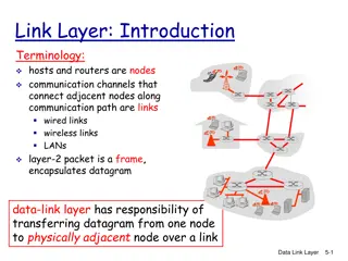
The link layer, an essential component in computer networks, is implemented at every host through adapters like NICs or Ethernet/802.11 cards. It handles tasks such as frame encapsulation, error checking, and flow control to ensure reliable data transmission between nodes. Link layer services include framing, link access, and error detection/correction, crucial for effective communication over different types of links. This layer plays a vital role in facilitating data transfer by encapsulating datagrams into frames and providing reliable delivery mechanisms.

Download Presentation

Please find below an Image/Link to download the presentation.
The content on the website is provided AS IS for your information and personal use only. It may not be sold, licensed, or shared on other websites without obtaining consent from the author. Download presentation by click this link. If you encounter any issues during the download, it is possible that the publisher has removed the file from their server.
E N D
Presentation Transcript
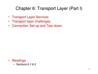
Course on Computer Communication and Networks Lectures 8 partb, 9 Chapter 5: Link Layer EDA344/DIT 420, CTH/GU Based on the book Computer Networking: A Top Down Approach, Jim Kurose, Keith Ross, Addison-Wesley. 1 M. Papatriantafilou Link Layer
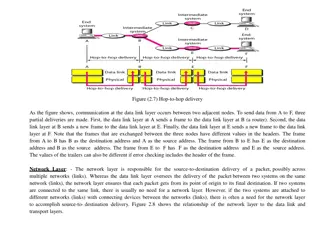
Link layer: context transportation analogy trip from Princeton to Lausanne limo: Princeton to JFK plane: JFK to Geneva train: Geneva to Lausanne tourist = datagram transport segment = communication link transportation mode = link layer protocol travel agent = routing algorithm Datagram transferred by different link protocols over different links: e.g., Ethernet on first link, frame relay on intermediate links, 802.11 on last link Each link protocol provides different services e.g., may or may not provide rdt over link 5: DataLink Layer 5-2 M. Papatriantafilou Link Layer
Where is the link layer implemented? at every host: in its adapter (aka network interface card NIC) Ethernet card, 802.11 card; Ethernet chipset implements link, physical layer attaches into host s system buses combination of hardware, software, firmware application transport network link cpu memory host bus (e.g., PCI) controller link physical physical transmission network adapter card -3 M. Papatriantafilou Link Layer
Adapters communicating datagram datagram controller controller receiving host sending host datagram frame receiving side looks for errors, rdt, flow control, etc extracts datagram, passes to upper layer at receiving side sending side: encapsulates datagram in frame adds error checking bits, rdt, flow control, etc. 4 M. Papatriantafilou Link Layer
Link layer services framing, link access: encapsulate datagram into frame (header, trailer) Link-layer addresses in frame headers to identify source, dest different from IP address! channel access if shared medium reliable delivery between adjacent nodes we learned how to do this already (chapter 3)! seldom used on low bit-error link (fiber, some twisted pair) wireless links: high error rates; error detection and correction applicable error detection: receiver detect errors caused by signal attenuation, noise. (possibly) error correction: receiver identifies and corrects bit error(s) without resorting to retransmission flow control: pacing between adjacent sending and receiving nodes 5-5 M. Papatriantafilou Link Layer
Roadmap 5.1 Introduction and services 5.4 Link-Layer Addressing LAN technology 5.5 Ethernet 5.6 Interconnection 5.3 Multiple access protocols 5.9 A day in the life of a web request (5.7 PPP 5.8 Link Virtualization: ATM and MPLS) Framing (5.2 Error detection and correction ) *grey items will be treated as complement, in subsequent lectures 5: DataLink Layer 5-6 M. Papatriantafilou Link Layer
LAN Addresses Different from 32-bit IP address: network-layer address used to get datagram to destination network (recall IP network definition) LAN (or MAC or physical) address: to get datagram from one interface to another physically-connected interface (same network) 48 bit MAC address (for most LANs) burned in NIC s ROM (sometimes configurable) Broadcast address = FF-FF-FF-FF-FF-FF 5-7 M. Papatriantafilou Link Layer
Recall earlier routing discussion Starting at A, given IP datagram addressed to B: A 223.1.1.1 223.1.2.1 223.1.1.2 look up net. address of B, find B on same net. as A link layer sends datagram to B inside link-layer frame 223.1.1.4 223.1.2.9 B 223.1.2.2 E 223.1.3.27 223.1.1.3 223.1.3.2 223.1.3.1 frame source, dest address datagram source, dest address A s IP addr B s IP addr A s MAC addr B s MAC addr IP payload datagram frame 8 M. Papatriantafilou Link Layer
ARP: Address Resolution Protocol Each IP node (Host, Router) on LAN has ARP Table: address mappings < IP address; MAC address; TTL> < .. > TTL (Time To Live): time to cache (typically 20 min) Question: how to determine MAC address of B given B s IP address? Broadcast address = FF-FF-FF-FF-FF-FF If B s address not present in A s ARP table: A broadcasts ARP query, containing B's IP address B receives ARP query, replies to A with its (B's) physical layer address A caches (saves) IP-to-physical address pairs in its ARP table until they time out soft state: information that times out unless refreshed 9 M. Papatriantafilou Link Layer
Addressing: routing to another LAN walkthrough: send datagram from A to B via R focus on addressing at IP (datagram) and link layer (frame) assume A knows B s IP address assume A knows IP address of first hop router, R (how?) assume A knows R s MAC address (how?) B A R 111.111.111.111 74-29-9C-E8-FF-55 222.222.222.222 49-BD-D2-C7-56-2A 222.222.222.220 1A-23-F9-CD-06-9B 111.111.111.110 E6-E9-00-17-BB-4B 222.222.222.221 88-B2-2F-54-1A-0F 111.111.111.112 CC-49-DE-D0-AB-7D 5-10 M. Papatriantafilou Link Layer
Addressing: routing to another LAN A creates IP datagram with IP source A, destination B A creates link-layer frame with R's MAC address as dest, frame contains A-to-B IP datagram MAC src: 74-29-9C-E8-FF-55 MAC dest: E6-E9-00-17-BB-4B IP src: 111.111.111.111 IP dest: 222.222.222.222 IP Eth Phy B A R 111.111.111.111 74-29-9C-E8-FF-55 222.222.222.222 49-BD-D2-C7-56-2A 222.222.222.220 1A-23-F9-CD-06-9B 111.111.111.110 E6-E9-00-17-BB-4B 222.222.222.221 88-B2-2F-54-1A-0F 111.111.111.112 CC-49-DE-D0-AB-7D 5-11 M. Papatriantafilou Link Layer
Addressing: routing to another LAN frame sent from A to R frame received at R, datagram removed, passed up to IP MAC src: 74-29-9C-E8-FF-55 MAC dest: E6-E9-00-17-BB-4B IP src: 111.111.111.111 IP dest: 222.222.222.222 IP src: 111.111.111.111 IP dest: 222.222.222.222 IP Eth Phy IP Eth Phy B A R 111.111.111.111 74-29-9C-E8-FF-55 222.222.222.222 49-BD-D2-C7-56-2A 222.222.222.220 1A-23-F9-CD-06-9B 111.111.111.110 E6-E9-00-17-BB-4B 222.222.222.221 88-B2-2F-54-1A-0F 111.111.111.112 CC-49-DE-D0-AB-7D 5-12 M. Papatriantafilou Link Layer
Addressing: routing to another LAN R forwards datagram with IP source A, destination B R creates link-layer frame with B's MAC address as dest, frame contains A-to-B IP datagram MAC src: 1A-23-F9-CD-06-9B MAC dest: 49-BD-D2-C7-56-2A IP src: 111.111.111.111 IP dest: 222.222.222.222 IP Eth Phy IP Eth Phy B A R 111.111.111.111 74-29-9C-E8-FF-55 222.222.222.222 49-BD-D2-C7-56-2A 222.222.222.220 1A-23-F9-CD-06-9B 111.111.111.110 E6-E9-00-17-BB-4B 222.222.222.221 88-B2-2F-54-1A-0F 111.111.111.112 CC-49-DE-D0-AB-7D 5-13 M. Papatriantafilou Link Layer
Addressing: routing to another LAN R forwards datagram with IP source A, destination B R creates link-layer frame with B's MAC address as dest, frame contains A-to-B IP datagram MAC src: 1A-23-F9-CD-06-9B MAC dest: 49-BD-D2-C7-56-2A IP src: 111.111.111.111 IP dest: 222.222.222.222 IP Eth Phy IP Eth Phy B A R 111.111.111.111 74-29-9C-E8-FF-55 222.222.222.222 49-BD-D2-C7-56-2A 222.222.222.220 1A-23-F9-CD-06-9B 111.111.111.110 E6-E9-00-17-BB-4B 222.222.222.221 88-B2-2F-54-1A-0F 111.111.111.112 CC-49-DE-D0-AB-7D 5-14 M. Papatriantafilou Link Layer
Addressing: routing to another LAN R forwards datagram with IP source A, destination B R creates link-layer frame with B's MAC address as dest, frame contains A-to-B IP datagram MAC src: 1A-23-F9-CD-06-9B MAC dest: 49-BD-D2-C7-56-2A IP src: 111.111.111.111 IP dest: 222.222.222.222 IP Eth Phy B A R 111.111.111.111 74-29-9C-E8-FF-55 222.222.222.222 49-BD-D2-C7-56-2A 222.222.222.220 1A-23-F9-CD-06-9B 111.111.111.110 E6-E9-00-17-BB-4B 222.222.222.221 88-B2-2F-54-1A-0F 111.111.111.112 CC-49-DE-D0-AB-7D 5-15 M. Papatriantafilou Link Layer
Roadmap 5.1 Introduction and services 5.4 Link-Layer Addressing LAN technology 5.5 Ethernet 5.6 Interconnection 5.3 Multiple access protocols 5.9 A day in the life of a web request (5.7 PPP 5.8 Link Virtualization: ATM and MPLS) Framing (5.2 Error detection and correction ) *grey items will be treated as complement, in subsequent lectures 5: DataLink Layer 5-16 M. Papatriantafilou Link Layer
access links, protocols two types of links : point-to-point PPP for dial-up access point-to-point link between Ethernet switch, host broadcast (shared wire or medium), eg old-fashioned Ethernet 802.11 wireless LAN shared RF (e.g., 802.11 WiFi) shared RF (satellite) shared wire (e.g., cabled Ethernet) humans at a cocktail party (shared air, acoustical) Link Layer 5-17 M. Papatriantafilou Link Layer
i.e. (Multiple access) single shared broadcast channel two or more simultaneous transmissions by nodes: interference collision if node receives two or more signals at the same time multiple access protocol distributed algorithm that determines how nodes share channel, i.e., determine when node can transmit communication about channel sharing must use channel itself! no out-of-band channel for coordination Link Layer 5-18 M. Papatriantafilou Link Layer
An ideal multiple access protocol given: broadcast channel of rate R bps desiderata: 1. when one node wants to transmit, it can send at rate R. 2. when M nodes want to transmit, each can send at average rate R/M 3. fully decentralized: no special node to coordinate transmissions no synchronization of clocks, slots 4. simple Link Layer 5-19 M. Papatriantafilou Link Layer
MAC protocols: taxonomy three broad classes: channel partitioning divide channel into smaller pieces (time slots, frequency, code) allocate piece to node for exclusive use random access channel not divided, allow collisions recover from collisions taking turns nodes take turns, but nodes with more to send can take longer turns Link Layer 5-20 M. Papatriantafilou Link Layer
Channel Partitioning MAC : TDMA, FDMA FDMA: frequency division multiple access TDMA: time division multiple access access to channel in "rounds" each station gets fixed length slot (length = pkt trans time) in each round unused slots go idle example: 6-station LAN, 1,3,4 have pkt, slots 2,5,6 idle each station assigned fixed frequency band unused transmission time in frequency bands goes idle example: 6-station LAN, 1,3,4 have pkt, frequency bands 2,5,6 idle frequency bands M. Papatriantafilou Link Layer
Channel Partitioning CDMA CDMA: Code Division Multiple Access allows each station to transmit over the entire frequency spectrum all the time. simultaneous transmissions are separated using coding theory. used mostly in wireless broadcast channels (cellular, satellite, etc) we will study it in the wireless context has been traditionally used in the military Observe: MUX = speak person-to-person in designated space CDMA = shout using different languages: the ones who know the language will get what you say 5-22 M. Papatriantafilou Link Layer
MAC protocols: taxonomy three broad classes: channel partitioning divide channel into smaller pieces (time slots, frequency, code) allocate piece to node for exclusive use random access channel not divided, allow collisions recover from collisions taking turns nodes take turns, but nodes with more to send can take longer turns Link Layer 5-23 M. Papatriantafilou Link Layer
Random access protocols when node has packet to send transmit at full channel data rate R. no a priori coordination among nodes random access MAC protocol specifies: how to detect collisions how to recover from collisions (e.g., via delayed retransmissions) examples of random access MAC protocols: slotted ALOHA ALOHA CSMA, CSMA/CD, CSMA/CA Link Layer 5-24 M. Papatriantafilou Link Layer
Slotted ALOHA operation: when node obtains fresh frame (from upper layer protocol), it transmits in next slot if no collision: ok if collision: node retransmits frame in each subsequent slot with prob. p until success assumptions: all frames same size time divided into equal size slots (time to transmit 1 frame) nodes start to transmit only at slot beginning nodes are synchronized if 2 or more nodes transmit in slot, all nodes detect collision Link Layer 5-25 M. Papatriantafilou Link Layer
Slotted ALOHA Cons collisions, wasting slots idle slots clock synchronization Pros single active node can continuously transmit at full rate of channel highly decentralized: only slots in nodes need to be in sync simple 5: DataLink Layer 5-26 M. Papatriantafilou Link Layer
Slotted Aloha efficiency Efficiency : long-run fraction of successful slots (many nodes, all with many frames to send) Q: max fraction of successful transmissions? A: Suppose N stations, each transmits in slot with probability p prob. successful transmission is: P[specific node succeeds]= p (1-p)(N-1) P[any of N nodes succeeds] = N p (1-p)(N-1) 5: DataLink Layer 5-27 M. Papatriantafilou Link Layer
Pure Aloha vs slotted Aloha P(success by any of N nodes) = N p . (1-p)2N= i.e. N p P(no other node transmits in [p0-1,p0] . P(no other node transmits in [p0,p0+1] 0.4 =(as n -> infty ) 1/(2e) = .18 Slotted Aloha 0.3 0.2 0.1 Pure Aloha 1.5 2.0 0.5 1.0 G = offered load = #frames per frame-time 5: DataLink Layer 5-28 M. Papatriantafilou Link Layer
CSMA: Carrier Sense Multiple Access CSMA: listen before transmit: If channel sensed busy, defer transmission back-off, random interval If/when channel sensed idle: p-persistent CSMA: transmit immediately with probability p; with probablility 1-p retry after random interval non-persistent CSMA: transmit after random interval human analogy: don t interrupt others! 5: DataLink Layer 5-29 M. Papatriantafilou Link Layer
CSMA collisions spatial layout of nodes along ethernet collisions can occur: Due to propagation delay, two nodes may not hear each other s transmission collision: entire packet transmission time wasted note: role of distance and propagation delay (d)in determining collision (collision-detection delay <= 2d) 5: DataLink Layer 5-30 M. Papatriantafilou Link Layer
CSMA/CD (Collision Detection) CSMA/CD: carrier sensing, deferral as in CSMA colliding transmissions aborted, reducing channel wastage persistent or non-persistent retransmission collision detection: easy in wired LANs: measure signal strengths, compare transmitted, received signals different in wireless LANs: transmitter/receiver not on simultaneously; collision at the receiver matters, not the sender human analogy: the polite conversationalist 5-31 M. Papatriantafilou Link Layer
MAC protocols: taxonomy three broad classes: channel partitioning divide channel into smaller pieces (time slots, frequency, code) allocate piece to node for exclusive use random access channel not divided, allow collisions recover from collisions taking turns nodes take turns, but nodes with more to send can take longer turns Link Layer 5-32 M. Papatriantafilou Link Layer
Trade-off in MAC: channel partitioning MAC protocols: share channel efficiently and fairly at high load inefficient at low load: delay in channel access, bandwidth allocated even if only 1 active node! Random access MAC protocols efficient at low load: single node can fully utilize channel high load: collision overhead taking turns protocols look for best of both worlds! 5: DataLink Layer 5-33 M. Papatriantafilou Link Layer
Taking Turns MAC protocols T Token passing: control token-frame passed from one node to next sequentially. not pure broadcast (nothing to send) T concerns: token overhead latency single point of failure (token) other: token bus; see extra slides @ end of lecture data 5-34 M. Papatriantafilou Link Layer
Summary of MAC protocols What do you do with shared media? Channel Partitioning, by time, frequency or code Random partitioning (dynamic), ALOHA, S-ALOHA, CSMA, CSMA/CD carrier sensing: easy in some technologies (wire), hard in others (wireless) CSMA/CD used in Ethernet CSMA/CA used in 802.11 (to be studied in wireless) Taking Turns token passing, Bluetooth 5: DataLink Layer 5-35 M. Papatriantafilou Link Layer
encore : MAC: Reservation-based protocols Distributed Polling Bit-map protocol time divided into slots begins with N short reservation slots (can also be through CSMA/XX) station with message to send posts reservation during its slot reservation seen by all stations after reservation slots, message transmissions ordered by known priority Used in DOCSIS: Data-over-cable Service interface (see next slide) 5: DataLink Layer 5-36 M. Papatriantafilou Link Layer
Cable access network cable headend MAP frame for Interval [t1, t2] Downstream channel i CMTS Upstream channel j t1 t2 Residences with cable modems Minislots containing minislots request frames Assigned minislots containing cable modem upstream data frames DOCSIS: data over cable service interface spec FDM over upstream, downstream frequency channels TDM upstream: some slots assigned, some have contention downstream MAP frame: assigns upstream slots request for upstream slots (and data) transmitted random access (binary backoff) in selected slots Link Layer 5-37 M. Papatriantafilou Link Layer
Roadmap 5.1 Introduction and services 5.4 Link-Layer Addressing LAN technology 5.5 Ethernet 5.6 Interconnection 5.3 Multiple access protocols 5.9 A day in the life of a web request (5.7 PPP 5.8 Link Virtualization: ATM and MPLS) Framing (5.2 Error detection and correction ) *grey items will be treated as complement, in subsequent lectures 5: DataLink Layer 5-38 M. Papatriantafilou Link Layer
Ethernet dominant wired LAN technology: cheap $20 for 100Mbs! first widely used LAN technology Simpler, cheaper than token LANs and ATM Kept up with speed race: 10 Mbps 100 Gbps Metcalfe s Ethernet sketch 5: DataLink Layer 5-39 M. Papatriantafilou Link Layer
Ethernet: uses CSMA/CD Repeat: sense channel, if idle then { transmit and monitor the channel; If detect collision then { abort and send jam signal; update # collisions m; delay as required by exponential backoff algorithm: choose backoff interval from {0, , 2^m} } else {SUCCSESS; done with the frame; set collisions to zero} } else {wait until colliding transmission is over} Until successful transmission 5: DataLink Layer 5-40 M. Papatriantafilou Link Layer
Exponential Backoff: Goal: adapt retransmission attempts to estimated current load heavy load: random wait will be longer 5: DataLink Layer 5-41 M. Papatriantafilou Link Layer
Ethernet (CSMA/CD) Limitation Recall: collision detection interval = 2*Propagation delay along the LAN This implies a minimum frame size and/or a maximum wire length Critical factor: a = 2 * propagation_delay / frame_transmission_delay 5: DataLink Layer 5-42 M. Papatriantafilou Link Layer
Star topology bus topology popular through mid 90s all nodes in same collision domain (can collide with each other) today: star topology prevails (more bps, shorter distances) Hub or active switch in center (more in a while) switch bus: coaxial cable star 5: DataLink Layer 5-43 M. Papatriantafilou Link Layer
Ethernet Frame Structure Sending adapter encapsulates IP datagram (or other network layer protocol packet) in Ethernet frame Preamble: 7 bytes with pattern 10101010 followed by one byte with pattern 10101011 to synchronize receiver and sender clock rates Addresses: 6 bytes, frame is received by all adapters on a LAN and dropped if address does not match Type: indicates the higher layer protocol, mostly IP but others may be supported CRC: checked at receiver, if error is detected, the frame is simply dropped 5: DataLink Layer 5-44 M. Papatriantafilou Link Layer
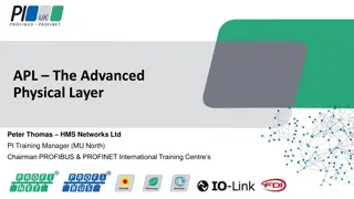
802.3 Ethernet Standards: Link & Physical Layers many different Ethernet standards common MAC protocol and frame format different speeds: 2 Mbps, 10 Mbps, 100 Mbps, 1Gbps, 10G bps different physical layer media: fiber, cable MAC protocol and frame format application transport network link physical 100BASE-T2 100BASE-FX 100BASE-TX 100BASE-BX 100BASE-SX 100BASE-T4 fiber physical layer copper (twisted pair) physical layer 5: DataLink Layer 5-45 M. Papatriantafilou Link Layer
Ethernet: Unreliable, connectionless connectionless: No handshaking between sending and receiving NICs unreliable: receiving NIC doesn t send acks or nacks to sending NIC stream of datagrams passed to network layer can have gaps (missing datagrams) gaps will be filled if app is using TCP otherwise, app will see gaps 5: DataLink Layer 5-46 M. Papatriantafilou Link Layer
Roadmap 5.1 Introduction and services 5.4 Link-Layer Addressing LAN technology 5.5 Ethernet 5.6 Interconnection 5.3 Multiple access protocols 5.9 A day in the life of a web request (5.7 PPP 5.8 Link Virtualization: ATM and MPLS) Framing (5.2 Error detection and correction ) *grey items will be treated as complement, in subsequent lectures 5: DataLink Layer 5-47 M. Papatriantafilou Link Layer
Interconnecting with hubs Hubs are essentially physical-layer repeaters: bits coming from one link go out all other links at the same rate (no frame buffering) no CSMA/CD at hub: adapters detect collisions (one large collision domain) provides net management functionality (monitoring, statistics) Extends distance between nodes Can t interconnect different standards, e.g. 10BaseT & 100BaseT hub hub hub hub http://www.youtube.com/watch?v=reXS_e3fTAk&feature=related (video link) 5: DataLink Layer 5-48 M. Papatriantafilou Link Layer
Switch: multiple simultaneous transmissions switches buffer packets Ethernet protocol used on each incoming link, but no collisions; full duplex each link is its own collision domain switching: A-to-A and B-to-B can transmit simultaneously, without collisions A B C 1 2 6 4 5 3 C B A forwarding: how to know LAN segment on which to forward frame? looks like a routing problem switch with six interfaces (1,2,3,4,5,6) Link Layer 5-49 M. Papatriantafilou Link Layer
Switch: self-learning Source: A Dest: A A A A switch learns which hosts can be reached through which interfaces when frame received, switch learns location of sender: incoming LAN segment records sender/location pair in switch table B C 1 2 6 4 5 3 C B A MAC addr interface TTL Switch table (initially empty) 60 1 A Link Layer 5-50 M. Papatriantafilou Link Layer


")


")


 Limitation")