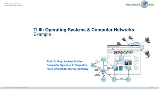
Overview of Prof. Dr.-Ing. Jochen Schiller's Operating Systems and Computer Networks Course
Prof. Dr.-Ing. Jochen Schiller teaches a course on Operating Systems and Computer Networks at Freie Universität Berlin, Germany. The course covers topics like Networked Computer & Internet, Host-to-Network communication, Transport Layer, Network Security, and more. Reasons for having multiple networks are discussed, along with details on internetworking units and repeater/hub functions in network communication.
- Prof. Dr. Jochen Schiller
- Operating Systems
- Computer Networks
- Freie Universität Berlin
- Internetworking

Download Presentation

Please find below an Image/Link to download the presentation.
The content on the website is provided AS IS for your information and personal use only. It may not be sold, licensed, or shared on other websites without obtaining consent from the author. Download presentation by click this link. If you encounter any issues during the download, it is possible that the publisher has removed the file from their server.
E N D
Presentation Transcript
Prof. Dr.-Ing. Jochen Schiller Computer Systems & Telematics TI III: Operating Systems & Computer Networks Internetworking 7 6 5 4 3 2 1 7 6 5 4 3 2 1 Prof. Dr.-Ing. Jochen Schiller Computer Systems & Telematics Freie Universit t Berlin, Germany TI 3: Operating Systems and Computer Networks 10.1
Content 8. Networked Computer & Internet 9. Host-to-Network 10. Internetworking 11. Transport Layer 12. Applications 13. Network Security 14. Example TI 3: Operating Systems and Computer Networks 10.2
Network Layer TI 3: Operating Systems and Computer Networks 10.3
Reasons for Multiple Networks Limited number of users/throughput in a single network Historical reasons: -Different groups started out individually setting up networks -Usually heterogeneous Geographic distribution of different groups over different buildings, campus, -Impractical/impossible to use a single network because of distance -Most MAC protocols set maximum segment length for medium access, e.g., CSMA/CD -Long round-trip delay will negatively influence performance Reliability -Don t put all your eggs into one basket - Babbling idiot problem (isolation of errors) Security -Contain possible damage caused by promiscuous operation Political / business reasons -Different authorities, policies, laws, levels of trust, TI 3: Operating Systems and Computer Networks 10.4
Internetworking Units WWW Server fiber HTTP Router Router TCP fiber fiber Proprietary Systems, Interior networks, IP Router Router LLC MAC PHY Repeater Notebook Firewall Gateway Repeater WWW-Browser fiber HTTP TCP Router IP IP Switch LLC LLC LLC LLC MAC (WLAN) MAC (WLAN) MAC (Ethernet) MAC (Ethernet) MAC (xyz) PHY PHY PHY PHY PHY Radio UTP5 Twisted Pair TI 3: Operating Systems and Computer Networks 10.5
Internetworking Units Gateway n 4 n 4 ... ... ... ... ... Router 4 4 4 4 4 Switch 3 3 3 3 3 3 3 3 3 Repeater 2 2 2 2 2 2 2 2 2 2 2 1 1 1 1 1 1 1 1 1 1 1 1 1 e.g. Deep sea cable Ethernets Internet Applications (email, ) TI 3: Operating Systems and Computer Networks 10.6
Repeater / Hub Simplest option: Repeater -Physical layer device, connected to two or more cables -Amplifies/regenerates arriving signal, puts on other cables -Combats attenuation Signal encodes data (represented by bits) -Can be regenerated -Opposed to only amplified (which would also amplify noise) Analog vs. digital transmission -Neither understands nor cares about content (bits) of packets Signal in Signal out Repeater Regeneration TI 3: Operating Systems and Computer Networks 10.7
Problems of Physical Layer Solutions Physical layer devices, e.g. repeater or hub, do not solve the more interesting problems -E.g. no mechanism for handling load, scalability, ... Some knowledge of data link layer structure is necessary -Ability to understand/inspect content of packets/frames and do something with that knowledge Link-layer devices: -Switch: Interconnect several terminals -Bridge: Interconnect several networks (of different type) Nowadays terms sometimes used interchangeably TI 3: Operating Systems and Computer Networks 10.8
Switch Used to connect several terminals or networks Switch inspects arriving packet s MAC addresses and forwards it only on correct cable/port -Does not bother other terminals -Requires data buffer and knowledge on which port which terminal is connected -Mapping function of MAC address to port How to obtain knowledge about network topology? -Observe from where packets come to decide how to reach sending terminal Backward learning TI 3: Operating Systems and Computer Networks 10.9
Backward Learning Algorithm Receive MAC frame no Store source addr. and port Source address known? Aging yes Update time-stamp Destination addr. known? yes no Forward on correct port Forward on all ports 1. Learn address/port mapping from incoming packets - Remove expired entries (aging) 2. Forward based on knowledge about destination address 1. Destination address is known 2. Destination address is unknown Only correct receiver will process frame, others will drop it Forward on correct port Forward on all ports TI 3: Operating Systems and Computer Networks 10.10
Questions & Tasks -How far can we (in theory) transmit data? -What can gateways do compared to the other interworking units? -Compare switch vs. hub what are differences / advantages / disadvantages? TI 3: Operating Systems and Computer Networks 10.13
Routers All devices so far either ignored addresses (repeaters, hubs) or worked on MAC-layer addresses (switches, bridges) For interconnection outside a single LAN or connection of LANs, these simple addresses are insufficient -Unstructured, flat addresses do not scale -All forwarding devices would need a list of all addresses -Structured network topologies do not scale -World-wide spanning tree is unfeasible Need more sophisticated addressing structure and devices that operate on it -Routers and routing -E.g. based on Internet Protocol (IP) addresses TI 3: Operating Systems and Computer Networks 10.14
Example: Route to NASA (redone) Z:\>tracert www.nasa.gov C:\>tracert www.nasa.gov Tracing route to www.nasa.gov.speedera.net [213.61.6.3] over a maximum of 30 hops: Tracing route to iznasa.hs.llnwd.net [2a02:3d0:623:a000::8008] over a maximum of 30 hops: 1 <1 ms 2 <1 ms 3 1 ms 4 1 ms 5 1 ms 6 9 ms 7 10 ms 8 10 ms <1 ms <1 ms <1 ms <1 ms <1 ms 9 ms 9 ms 9 ms <1 ms <1 ms <1 ms <1 ms <1 ms 9 ms 9 ms 9 ms router-114.inf.fu-berlin.de [160.45.114.1] zedat.router.fu-berlin.de [160.45.252.181] ice.spine.fu-berlin.de [130.133.98.2] ar-fuberlin1.g-win.dfn.de [188.1.33.33] cr-berlin1-po5-0.g-win.dfn.de [188.1.20.5] cr-frankfurt1-po9-2.g-win.dfn.de [188.1.18.185] ir-frankfurt2-po3-0.g-win.dfn.de [188.1.80.38] DECIX.fe0-0-guy-smiley.FFM.router.COLT.net 1 <1 ms <1 ms <1 ms router-714.imp.fu-berlin.de 2 <1 ms <1 ms <1 ms 2001:638:80a:1::1 3 1 ms 1 ms <1 ms 2001:638:80a:3::1 4 * * * Request timed out. 5 10 ms 10 ms 11 ms 2001:7f8:8::5926:0:1 6 17 ms 17 ms 17 ms tge1-4.fr5.dus1.ipv6.llnw.net 7 12 ms 47 ms 12 ms tge3-4.fr4.fra1.ipv6.llnw.net 8 12 ms 12 ms 12 ms 2a02:3d0:623:6d::2 9 15 ms 12 ms 12 ms https-2a02-3d0-623-a000--8008.fra.ipv6.llnw.net [2a02:3d0:623:a000::8008] [2001:638:80a:105::1] [2a02:3d0:622:6c::2] [80.81.192.61] 9 10 ms 10 11 ms 11 11 ms 12 11 ms 9 ms 10 ms 10 ms 10 ms 9 ms 9 ms 10 ms 10 ms ir1.fra.de.colt.net [213.61.46.70] ge2-2.ar06.fra.DE.COLT-ISC.NET [213.61.63.8] 213.61.4.141 h-213.61.6.3.host.de.colt.net [213.61.6.3] [2607:f4e8:1:c6::1] Trace complete. Trace complete. Not all addresses can be resolved to names (see DNS) Some requests are redirected to Content Delivery Networks What happened here? Some nodes simply don t answer TI 3: Operating Systems and Computer Networks 10.15
The Idea of Internet Routing Routing comprises: -Updating of routing tables according to routing algorithm -Exchange of routing information using routing protocol -Forwarding of data based on routing tables and addresses Inter Domain Routing Intra Domain Routing Large company Consumer ISP 1 Peering point Backbone service provider 2 Consumer ISP 2 Small company 1 Small company 2 TI 3: Operating Systems and Computer Networks 10.16
Autonomous Systems in the IP World Large organizations can own multiple networks that are under single administrative control Forming autonomous system or routing domain Autonomous systems form yet another level of aggregating routing information Give raise to inter- and intra-domain routing Inter-domain routing is hard -One organization might not be interested in carrying a competitor s traffic -Routing metrics of different domains cannot be compared Only reachability can be expressed -Scalability: Currently, inter-domain routers have to know about 200,000 400,000 networks TI 3: Operating Systems and Computer Networks 10.17
Intra-domain Routing: OSPF The Internet s most prevalent intra-domain (= interior gateway) routing protocol: Open Shortest Path First (OSPF) Main properties: -Open, variety of routing distances, dynamic algorithm -Routing based on traffic type (e.g. real-time traffic uses different paths) -Load balancing: Also put some packets on the 2nd, 3rd best path -Hierarchical routing, some security in place, support tunneled routers in transit networks Essential operation: Compute shortest paths on graph abstraction of autonomous system Link state algorithm TI 3: Operating Systems and Computer Networks 10.18
Basic Ideas of Link State Routing Distributed, adaptive routing Algorithm: 1. Discovery of new neighbors - HELLO packet 2. Measurement of delay / cost to all neighbors - ECHO packet measures round trip time 3. Creation of link state packets containing all learned data - Sender and list of neighbors (including delay, age, ...) - Periodic or event triggered update (e.g. upon detecting new neighbors, line failure, ...) 4. Flooding of packet to all neighbors - Flooding, but with enhancements: Duplicate removal, deletion of old packets, ... 5. Shortest path calculation to all other routers (e.g. Dijkstra) - Computing intensive, optimizations exist TI 3: Operating Systems and Computer Networks 10.19
Inter-domain Routing: BGPv4 Routing between domains: Border Gateway Protocols (BGP) BGP s perspective: Only autonomous systems and their connections -Routing complicated by politics, e.g. only route packets for paying customers, -Legal constraints, e.g. traffic originating and ending in Canada must not leave Canada while in transit Basic operation: Distance vector protocol -Propagate information about reachable networks and distances one hop at a time -Each router learns only next step to destination -Optimizations in BGP: -Not only keep track of cost via a given neighbor, but store entire paths to destination ASs -> Path vector protocol -More robust, solves problems like count to infinity, i.e. can handle disconnected networks efficiently TI 3: Operating Systems and Computer Networks 10.20
Conclusion: Interconnections Single LANs are insufficient to provide communication for all but the simplest installations Interconnection of LANs necessary -Interconnect on purely physical layer: Repeater, hub -Interconnect on data link layer: Bridges, switches -Interconnect on network layer: Router -Interconnect on higher layer: Gateway Problems: -Redundant bridges can cause traffic floods; need spanning tree algorithm -Simple addresses do not scale; need routers TI 3: Operating Systems and Computer Networks 10.21
Questions & Tasks -We can t we set-up a large scale network based on layer 2? Why is this possible on layer 3? -What is the difference between intra- and inter-domain routing? What are typical protocols for it? -Why does BGP not always give the shortest path? -Why not using OSPF for world-wide routing? TI 3: Operating Systems and Computer Networks 10.22
INTERNET PROTOCOL TI 3: Operating Systems and Computer Networks 10.23
Simplified View of Internet protocols Internet Application Application TCP UDP TCP UDP Host A Host B IP IP Host-to- Network Host-to- Network TI 3: Operating Systems and Computer Networks 10.24
IP and Supporting Protocols Transport protocols (Layer 4, TCP or UDP) hand over data together with IP address of receiver to Internet Protocol (IP) IP may need to ask Address Resolution Protocol (ARP) for MAC address (Layer 2) IP hands over data together with MAC address to Layer 2 IP forwards data to higher layers (TCP or UDP) Internet Control Message Protocol (ICMP) can signal problems during transmission TCP UDP 4 3 ICMP ARP IP Host-to-Network 2 TI 3: Operating Systems and Computer Networks 10.25
Data Encapsulation / Decapsulation IP forwards data packets through network to receiver TCP/UDP add ports (dynamic addresses of processes) TCP offers reliable data transmission Packets (PDU, protocol data unit) are encapsulated data >4 User TCP header data 4 Transport layer or UDP header data IP header TCP/UDP header data 3 Network layer 2 Data link layer MAC/LLC header IP header TCP/UDP header data trailer TI 3: Operating Systems and Computer Networks 10.26
Internet Protocol (IP) History -Original development with support of US Department of Defense -Already used back in 1969 in APANET Per country IPv6 adoption as seen by Google Tasks -Routing support using structured addresses -Checking of packet lifetime to avoid routing loops -Fragmentation and reassembly -Network diagnostics support Development -Today IP (version 4) is still most widely used layer 3 protocol -Further development started back in the 80s/90s -Project IPng (IP next generation) of the IETF (Internet Engineering Task Force) -Result in mid 90s: IPv6, still not as widely used as expected -Today widely used, but could be more -E.g., 2020: about 32% access Google via IPv6 (Germany 50%, USA 41%, Sweden 6%) Source: www.google.com TI 3: Operating Systems and Computer Networks 10.27
Properties of IP Packet oriented Connectionless (datagram service) Unreliable transmission -Datagrams can be lost -Datagrams can be duplicated -Datagrams can be reordered -Datagrams can circle, but solved by Time to Live (TTL) field -IP cannot handle Layer 2 errors -At least there is ICMP to signal errors Routing support via structured addresses No flow control (yet, first steps taken) Used in private and public networks TI 3: Operating Systems and Computer Networks 10.28
IPv4 Datagram Bit 0 3 7 15 31 Version Hdr.Len DiffServ Total Length Identifier Flags Fragment Offset Time to Live Protocol Header Checksum IP Header Source Address Destination Address Options and Padding Data TI 3: Operating Systems and Computer Networks 10.29
IPv4 Datagram Congestion control (Explicit Congestion Notification) Don t Fragment Reserved More Fragments QoS class DiffServ Codepoint ECN 0 DF MF Bit 0 3 7 15 31 Version Hdr.Len DiffServ Total Length Identifier Flags Fragment Offset Time to Live Protocol Header Checksum IP Header Source Address Destination Address Options and Padding Data TI 3: Operating Systems and Computer Networks 10.30
Structured IP Addresses and Address Classes (Classical View) 1. Class A: 128 networks, 16M hosts 0 1 2 4 8 16 24 31 0 Network ID Host ID 1.0.0.0 127.255.255.255 2. Class B: 16k networks, 64k hosts 1 0 Network ID Host ID 128.0.0.0 191.255.255.255 3. Class C: 2M networks, 256 hosts 1 1 0 Network ID HostID 192.0.0.0 223.255.255.255 4. Class D: group communication (Multicast) 1 1 1 0 Multicast address 224.0.0.0 239.255.255.255 5. Class E: reserved for future use 1 1 1 1 0 Reserved 240.0.0.0 255.255.255.255 TI 3: Operating Systems and Computer Networks 10.31
Special IP Addresses Some IP addresses are reserved for special uses: Not all of the network/host combinations are available So-called private IP addresses -Used for internal networks (addresses not routable) -Example: 10.0.0.1, 192.168.0.1 TI 3: Operating Systems and Computer Networks 10.32
Questions & Tasks -What service does IP offer? -Which protocols are needed in addition for what purpose? -Why does it take that long before everyone uses IPv6? What is needed? -How to stop circulating packets? -What is the problem of the classical class-based addressing? (That s why we have CIDR ) -What is the purpose of private addresses? TI 3: Operating Systems and Computer Networks 10.33
Bridging Addressing Gap: ARP What happens once a packet arrives at its destination network / LAN? -IP address (which is all that is known about destination) needs to be translated into a MAC address that corresponds to the IP address Simple solution: Broadcast -Broadcast on LAN, asking which node has requested IP address -Node answers with its MAC address -Router can then forward packet to that MAC address Address Resolution Protocol (ARP) TI 3: Operating Systems and Computer Networks 10.34
Example: ARP 129.13.35.71 Wanted: Hardware address of 129.13.35.73 IP ARP (1) Host 129.13.35.71 is looking for host 129.13.35.73 ARP ARP (2) I am host 129.13.35.73 and my MAC address is 08-00- 2b-a2-80-dd 129.13.35.73 129.13.35.75 TI 3: Operating Systems and Computer Networks 10.35
Scalability Problems of IP Class A and B networks can contain many hosts -Too many for a router to easily deal with -Additionally, administrative problems in larger networks Solution: Subnetting, i.e. a network is subdivided into several smaller networks by breaking up the address space Network classes waste a lot of addresses -Example: Organization with 2000 hosts requires a class B address, wasting 64K-2K 62.000 host addresses Solution: Classless addressing Classless Inter Domain Routing (CIDR) -Dynamic boundaries between host/network part of IP address -Aggregation on routers to reduce size of global routing table TI 3: Operating Systems and Computer Networks 10.36
Subnetting Suppose an organization has one class B address but is organized into several LANs -Example: University with different departments Main router should be concerned with whole networks -Should not be bothered with all the nodes in each departments Obvious case for hierarchical routing and addressing How to put hierarchies into existing IP addresses? TI 3: Operating Systems and Computer Networks 10.37
Subnetting Hierarchies in Addresses Manipulating class bits to introduce more hierarchy levels is not practical Idea: Have more hierarchy levels implicitly -Introduce a subnet, represented by borrowing bits from host part of IP address -Local router has to know where to apply this split -Needs a subnet mask -Represented as x.y.u/#bits or as bit pattern needed to mask out the host bits Original host part TI 3: Operating Systems and Computer Networks 10.38
Controling IP: ICMP IP is responsible for (unreliable) data transfer only Internet Control Message Protocol (ICMP) is used for error reporting and testing Router line Router Router interupted Router Receiver Sender ICMP messages Examples: -Destination Unreachable -Time Exceeded: Time-to-Live field reaches 0 -Also used when looking up routes using traceroute -Echo Request / Reply ("ping") -Timestamp Request / Reply TI 3: Operating Systems and Computer Networks 10.39
Conclusion: Internet Protocol Unreliable datagram transfer Needs supporting protocols -ARP for mapping IP to MAC address -ICMP for error signaling Classical addressing wastes addresses -Subnetting, subnet masks -Classless addressing, CIDR Version 4 dominant, version 6 coming (since years ) -Much more in Telematics TI 3: Operating Systems and Computer Networks 10.40
Content 8. Networked Computer & Internet 9. Host-to-Network 10. Internetworking 11. Transport Layer 12. Applications 13. Network Security 14. Example TI 3: Operating Systems and Computer Networks 10.41
Questions & Tasks -Assume you are in Berlin and want to send an IP-packet to a computer in Tokyo. Which destination MAC- address will the outgoing packet contain? Why? How does the computer know this address? -How does CIDR help to reduce wasted addresses and routing overhead? -How can subnetting help? Which part of the address can be subnetted ? -What is the role of ICMP? TI 3: Operating Systems and Computer Networks 10.42


")


")