Fundamentals of Data Link Layer and Ethernet in Computer Networks

Delve into the essential concepts of the Data Link Layer and Ethernet in computer networking, covering services like framing, error detection, correction, reliable delivery, and more. Explore how frames transfer data between nodes, the importance of link protocols, and the role of MAC protocols in link access control for point-to-point and broadcast channels.

Download Presentation

Please find below an Image/Link to download the presentation.
The content on the website is provided AS IS for your information and personal use only. It may not be sold, licensed, or shared on other websites without obtaining consent from the author. Download presentation by click this link. If you encounter any issues during the download, it is possible that the publisher has removed the file from their server.
E N D
Presentation Transcript
Link Layer and Ethernet Credit: 14-740: Fundamentals of Computer Networks Bill Nace Material from Computer Networking: A Top Down Approach, 6thedition. J.F. Kurose and K.W. Ross
traceroute Data Link Layer Multiple (Media / Medium) Access Protocols Ethernet 14-740: Fall 2017 3
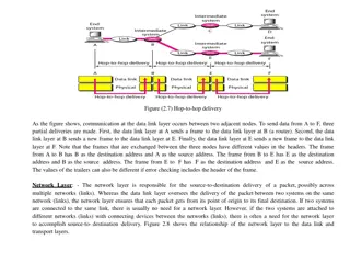
Data Link Layer Mission The Data Link Layer transfers frames from one node, over a link, to an adjacent node i.e. service provided to network layer Service received from physical layer is the ability to move a bit across the link 14-740: Fall 2017 4
Data Link Layer Link layer data is called a frame and will encapsulate a network layer datagram Link: Communication channel that connects adjacent nodes (host or router) Point-to-Point Broadcast Router has multiple link layers (one per interface) Each link is a subnet
Context A packet is transferred by different link protocols over different links e.g., Ethernet on first link, frame relay on intermediate links, 802.11 on last link Each data link protocol provides different services e.g., may or may not provide reliable data transfer over link
Link Layer Services Framing: encapsulate datagram into frame, adding header, trailer identify source, destination with addresses Different from IP addresses!! Link access: use medium access control (MAC) protocol Point-to-point channels: this is trivial Broadcast channels: more interesting 14-740: Fall 2017 7
Link Layer Services (2) Error Detection: errors caused by signal attenuation, noise, crosstalk, etc if receiver detects errors, signals for retransmission or drops frame Error Correction: receiver identifies and corrects bit error(s) without resorting to retransmission 14-740: Fall 2017 8
Link Layer Services (3) Reliable Delivery: between adjacent nodes similar to Reliable Data Transport seldom used on low bit-error links (fiber, twisted pair) critical for wireless links high error rates 14-740: Fall 2017 9
MTU Remember Max Transmission Unit? A value derived from the technology of the data-link layer The largest number of bytes carried in the payload of a frame Does not include the link-layer header or trailer 14-740: Fall 2017 10
traceroute Data Link Layer Multiple (Media / Medium) Access Protocols Ethernet 14-740: Fall 2017 11
Two Types of Links Point-to-point (sender to receiver) point-to-point link between Ethernet switch and host Point-to-Point Protocol (PPP) used to negotiate, establish, authenticate, etc Broadcast (shared wire or medium) traditional Ethernet 802.11 wireless LAN 14-740: Fall 2017 12
Medium Access Control Protocols For a single shared broadcast channel Simultaneous transmissions by 2 or more nodes interference collision if node receives two or more signals at the same time Multiple access protocol: a distributed algorithm that determines how nodes share channel communication about channel sharing must use channel itself! 14-740: Fall 2017 13
MAC Protocols: A Taxonomy Channel Partitioning Taking Turns Random Access 14-740: Fall 2017 14
Channel Partitioning Divide the channel into pieces time slots, frequency, or code Let each node use a piece of the channel Each node gets R/N bps, where R is channel throughput, N is # of nodes BUT: If < N nodes want to send, they still only get R/N bps 14-740: Fall 2017 15
Taking Turns Taking Turns Like a time slot partition scheme ... but, nodes with more to send can take longer turns Polling Protocol Master node asks each node in turn to send Examples: 802.15 and Bluetooth Token-passing Special-purpose frame is passed in fixed order from node to node (pattern repeats indefinitely) Only the node with the token may send Examples: FDDI and 802.5 (token-ring) 14-740: Fall 2017 16
Random Access Transmitting node always sends at R bps Multiple nodes can send simultaneously Collision Collisions can be avoided or detected Avoided: Wireless, LocalTalk Detected: CSMA/CD Protocols 14-740: Fall 2017 17
CSMA / CD Carrier Sense: Listen before talking Multiple Access: Broadcast Medium Collision Detection: Listen as you talk. If you hear someone else, be quiet Ethernet is the most famous example 14-740: Fall 2017 18
CSMA / CD Overview Before transmitting, listen If channel is sensed idle, send the frame Else, defer transmission a random time If collision is detected, abort transmission reduces channel wastage 14-740: Fall 2017 19
Collision Detection Easy in wired LANs Measure signal strengths, compare the transmitted and received signals Difficult in wireless LANs Receiver is shut off during transmission Hidden terminal problem You may not hear transmission from someone out of your range, but others will 14-740: Fall 2017 20
Capturing a Channel Transmission is vulnerable for 1 propagation delay collision could occur If no other station initiates transmission during this period, sender has captured the channel No other node will initiate send Node transmits at t=0 Node captures channel at t=tprop
Space-Time Diagrams Illustrate propagation delay of message through the channel Message transmission time
Multiple Transmitters Signals mix, collision detected!
Detecting Collisions Min transmission time must be long enough for collisions to propagate
traceroute Data Link Layer Multiple (Media / Medium) Access Protocols Ethernet 14-740: Fall 2017 25
History Developed at Xerox PARC, 1974-5ish By Robert Metcalfe, David Boggs, Chuck Thacker and Butler Lampson Metcalfe founded 3Com and popularized Quickly became the dominant LAN technology Standardized as IEEE 802.3 Originally 3Mbps, now up to 100Gbps 400Gbps expected 2017 14-740: Fall 2017 26
Ethernet Services Connectionless No handshaking Unreliable Damaged frames are discarded No ACK or NACK generated by receiver In-order delivery 14-740: Fall 2017 27
Topology Bus Topology: shared cable 14-740: Fall 2017 28
Topology (2) Star Topology High-Speed backplane or interconnection fabric 14-740: Fall 2017 29
Ethernet Frame Preamble: 8 bytes 7 bytes with pattern 10101010 followed by one byte with pattern 10101011 used to synchronize receiver, sender clock rates 14-740: Fall 2017 30
Ethernet Frame Dest, Source Addresses: 6 bytes each Flat address space, globally unique 3 bytes indicate adapter manufacturer 3 bytes generated uniquely Watch out: Can be changed/spoofed Broadcast address exists 14-740: Fall 2017 31
Ethernet Frame Type: 2 bytes Indicates the network-layer protocol Mostly IP, ARP Others include Novell IXP, AppleTalk 14-740: Fall 2017 32
Ethernet Frame Data: 46-1500 bytes Encapsulated datagram Short datagrams padded to 46 bytes IP receiver discards based on datagram length field in IP header 14-740: Fall 2017 33
Ethernet Frame CRC: 4 bytes Error Checking Receiver will check simply discard frame on error 14-740: Fall 2017 34
Ethernet Frame Total Frame Min size: 64 bytes + preamble = 72 bytes Long enough to guarantee collision detection in max length cable (100m) Max size: 1518 bytes + preamble Short enough to minimize wait times, receiver buffer requirements 14-740: Fall 2017 35
Tx Algorithm 1.Ethernet adapter receives datagram from network-layer and builds frame Source address is MAC of sending adapter Destination address chosen based on IP address Address Resolution Protocol (ARP) Generates CRC often via H/W as frame is sent 14-740: Fall 2017 36
Alg: Carrier Sense 2.Adapter listens for 96 bit times of idle channel (Length of interframe gap) Bit time is .1uSec for 10Mbps Ethernet Variants exist for 1Mbps - 10Gbps If channel is idle, then transmit the frame If not idle, wait for it to be idle for 96 bit times 14-740: Fall 2017 37
Alg: Collision Detection 3.While transmitting, listen and compare to sending values If no difference, great If collision, abort and send jam signal 48 bit times long Inform other transmitters of collision 14-740: Fall 2017 38
Alg: Exponential Backoff 4.If collision happens, wait a random time before attempting transmission again For nthcollision in a row, m=min{n,10} choose random value K from {0..2m-1} {0,1} then {0,1,2,3} ... {0..1023} wait 512 K bit times before going back to step number 2 (carrier sense) After 16 collisions, give up 14-740: Fall 2017 39
Question #1 For 10Mbps Ethernet, what is the maximum wait time after a collision? Max random number (K) chosen is 1023 Wait time = K * 512 bit times = 1023 * 512 * .1uSec = 52377.6 uSec .05 sec 14-740: Fall 2017 41
Question #2 A and B are on a 10 Mbps segment. What is the max separation to still guarantee collision detection? Worst case: A sends min size frame at t=0. B starts sending just as A s frame arrives. B s signal must get to A before it finishes transmission Minimum size frame is 72 bytes = 576 bits If separation is s bit times, B starts sending at t=s B s signal arrives at A at t=2s at which time A must still have > 1 bit to send Therefore, s must be < (576-1)/2 bit times or 28.75 uS 14-740: Fall 2017 43
Question #3 At t=0, A and B (who are separated by 200 bit times) each try to transmit a frame with 1500 bytes of data. A collision occurs, after which Ka = 0 and Kb = 1. At what time will B start retransmitting the frame? 14-740: Fall 2017 45
Answer Time Event at A Event at B t = 0 Start sending Start Sending t = 200 B s message arrives, collision A s message arrives, collision t = 201 Send Jam signal Send Jam signal t = 248 Stop sending Jam Stop sending Jam wait 0 *512 bit times wait 1 * 512 bit times (until 760) t = 249 Still hearing B s message Still hearing A s message t = 400 Stop hearing B s message Stop hearing A s message t = 401 Start hearing B s Jam Start hearing A s Jam t = 448 Stop hearing B s Jam Stop hearing A s Jam t = 449 Listen for 96 bit times t = 545 Start sending t = 745 Start hearing A s Message
Answer Time Event at A Event at B t = 760 stop waiting Channel not idle 1500 byte (12000 bit) message ends. Stop transmitting t = 12545 t = 12745 Stop hearing A s message Still listening for idle channel Channel has been idle for 96 bit times t = 12841 Start Sending
Lesson Objectives Now, you should be able to: describe the mission, scope, addressing mechanism, data types and services /responsibilities of the Data Link Layer describe the differences between broadcast and point-to-point links describe three different general types of media access protocols 14-740: Fall 2017 48
You should be able to: describe the CSMA/CD protocol, including the details of Ethernet's implementation use space-time diagrams to describe or solve problems relating to media access, including details of Ethernet's implementation describe the Ethernet frame format solve problems involving interaction of several Ethernet senders and receivers, collisions, propagation times, and the details of Ethernet's CSMA/CD algorithm


")
")


")