Understanding Data Link Layer Communication in Computer Networks

Exploring the data link layer in computer networks, this lecture discusses the node-to-node communication, services provided, such as framing, flow control, error control, and congestion control. Through a series of images, the concept of links and nodes, as well as the responsibilities of the data link layer, are elucidated.

Download Presentation

Please find below an Image/Link to download the presentation.
The content on the website is provided AS IS for your information and personal use only. It may not be sold, licensed, or shared on other websites without obtaining consent from the author. Download presentation by click this link. If you encounter any issues during the download, it is possible that the publisher has removed the file from their server.
E N D
Presentation Transcript
Computer Networks By Sadiq Shah Lecture 10 (Chapter 9) FATA University
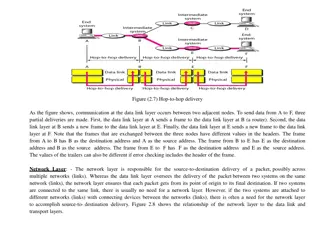
Nodes and Links Communication at the data-link layer is node-to-node. A data unit from one point in the Internet needs to pass through many networks (LANs and WANs) to reach another point. Theses LANs and WANs are connected by routers. Figure 9.2 is a simple representation of links and nodes when the path of the data unit is only six nodes.
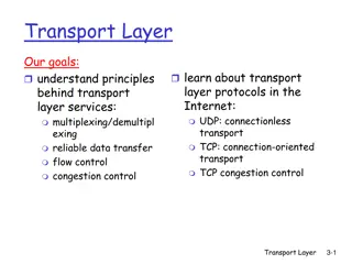
Services The data-link layer is located between the physical and the network layers. The datalink layer provides services to the network layer; it receives services from the physical layer. Let us discuss services provided by the data-link layer. When a packet is travelling in the Internet, the data-link layer of a node (host or router) is responsible for delivering a datagram to the next node in the path. The services list is given as; 1. Framing 2. Flow Control Control 3. Error Control Control 4. Congestion Control 2. Flow 3. Error 4. Congestion Control
1. Framing The first service provided by the data-link layer is framing. The data-link layer at each node needs to encapsulate the datagram (packet received from the network layer) in a frame before sending it to the next node.
2. Flow 2. Flow Control Control Whenever we have a producer and a consumer, we need to think about flow control. If the producer produces items that cannot be consumed, accumulation of items occurs. The sending data-link layer at the end of a link is a producer of frames; the receiving data-link layer at the other end of a link is a consumer. If the rate of produced frames is higher than the rate of consumed frames, frames at the receiving end need to be buffered while waiting to be consumed (processed). We have two choices. The first choice is to let the receiving data-link layer drop the frames if its buffer is full. The second choice is to let the receiving data-link layer send a feedback to the sending data-link layer to ask it to stop or slow down.
3. Error 3. Error Control Control At the sending node, a frame in a data-link layer needs to be changed to bits, transformed to electromagnetic signals, and transmitted through the transmission media. Since electromagnetic signals are susceptible to error, a frame is susceptible to error. The error needs first to be detected. After detection, it needs to be either corrected at the receiver node or discarded and retransmitted by the sending node.
4. Congestion 4. Congestion Control Control Although a link may be congested with frames, which may result in frame loss. In general, congestion control is considered an issue in the network layer or the transport layer because of its end-to- end nature. We will discuss congestion control in the network layer and the transport layer in later
LINK-LAYER ADDRESSING The link-layer addresses of the two nodes. A link-layer address is sometimes called a link address, sometimes a physical address, and sometimes a MAC address. When a datagram passes from the network layer to the data-link layer, the datagram will be encapsulated in a frame and two data-link addresses are added to the frame header. These two addresses are changed every time the frame moves from one link to another.
IP addresses and link-layer addresses in a small internet We have three links and two routers. We also have shown only two hosts: Alice (source) and Bob (destination). For each host, we have shown two addresses, the IP addresses (N) and the link-layer addresses (L). Each frame carries the same datagram with the same source and destination addresses (N1 and N8), but the link-layer addresses of the frame change from link to link.
Three Types of addresses Link-layer protocols define three types of addresses: unicast, multicast, and broadcast. Unicast Address Each host or each interface of a router is assigned a unicast address. Unicasting means one-to-one communication. A frame with a unicast address destination is destined only for one entity in the link. The unicast link-layer addresses in the most common LAN, Ethernet, are 48 bits (six bytes) that are presented as 12 hexadecimal digits separated by colons;
Multicast Address Some link-layer protocols define multicast addresses. Multicasting means one-to-many communication. However, the jurisdiction is local in LAN. The multicast link-layer addresses in the most common LAN, Ethernet, are 48 bits (six bytes) that are presented as 12 hexadecimal digits separated by colons;
Broadcast Address Some link-layer protocols define a broadcast address. Broadcasting means one-to-all communication. A frame with a destination broadcast address is sent to all entities in the link. The broadcast link-layer addresses in the most common LAN, Ethernet, are 48 bits (six bytes) that are presented as 12 hexadecimal digits separated by colons;