Understanding Computer Networks in BCA VI Semester

Computer networks are vital for sharing resources, exchanging files, and enabling electronic communications. This content explores the basics of computer networks, the components involved, advantages like file sharing and resource sharing, and different network computing models such as centralized and distributed computing. The importance of protocols, networking interface cards, and the flexibility networks offer are also discussed.

Download Presentation

Please find below an Image/Link to download the presentation.
The content on the website is provided AS IS for your information and personal use only. It may not be sold, licensed, or shared on other websites without obtaining consent from the author. Download presentation by click this link. If you encounter any issues during the download, it is possible that the publisher has removed the file from their server.
E N D
Presentation Transcript
IDHAYA COLLEGE FOR WOMEN KUMBAKONAM COMPUTER NETWORKS BCA - VI Semester SUB.CODE 16SCCCA8 PART 1 UNIT I - II 1
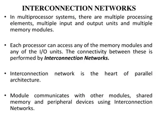
UNIT I Computer Networks A network consists of two or more computers that are linked in order to share resources (such as printers and CDs), exchange files, or allow electronic communications. The computers on a network may be linked through cables, telephone lines, radio waves, satellites etc. A popular example of a computer network is the Internet, which allows millions of users to share information. 2
Every Network Includes: At least two computers that have something to share. 1. A Transmission Media, for computers to signal each other. cable or wireless pathway, called 2. Rules, called Protocols, so that computers can use the unified principle of data communication. 3. Networking Interface Cards (NIC) 4. 4
Advantages of Computer Networks File Sharing: Networks offer a quick and easy way to share files directly. Resource Sharing: All computers in the network can share resources such as printers, fax machines, modems and scanners. Communication: Those on the network can communicate with each other via e-mail, instant messages etc. 5
Advantages of Computer Networks (Cont ) Flexible Access: Networks allow their users to access files from computers throughout the network. Sharing of Information: Computer networks enable us to share data and information with the computers that are located geographically large distance apart. 6
Network Computing Models Centralized Computing (Client-Server Network) A client-server network is where every client is connected to the server . Server or mainframe computer has huge storage and processing capabilities. 7
Network Computing Models Distributed Computing (Peer-to-Peer Network) All devices have same power. It interconnects one or more computers. Centralized backup is not possible. 8
Uses of Computer Network Simultaneous Access Shared Peripheral Devices Personal Communication Easier Backup 9
APPLICATIONS OF NETWOKS E-mail Searchable Data (Web Sites) E-Commerce News Groups Internet Telephony (VoIP) Video Conferencing Chat Groups Instant Messengers Internet Radio 10
What is a Topology? Network topologies describe the ways in which the elements of a network are mapped. They describe the physical and logical arrangement of the network nodes. The physical topology of a network refers to the configuration of cables, computers, and other peripherals 11
Different Types of Topologies Bus Topology Star Topology Ring Topology Mesh Topology Tree Topology Hybrid Topology 12
Bus Topology All the nodes (file server, workstations, and peripherals) on a bus topology are connected by one single cable. A bus topology consists of a main run of cable with a terminator at each end. All nodes (file server, peripherals) are connected to the linear cable. workstations, and Popular on LANs because they are inexpensive and easy to install. 13
Bus Topology 14
Ring Topology In a ring network, every device has exactly two neighbours for communication purposes. All messages travel through a ring in the same direction. A failure in any cable or device breaks the loop and can take down the entire network. To implement a ring network we use the Token Ring technology A token, or small data packet, is continuously passed around the network. When a device needs to transmit, it reserves the token for the next trip around, then attaches its data packet to it. 15
Star Topology In a star network, each node (file server, workstations, and peripherals) is connected to a central device called a hub. The hub takes a signal that comes from any node and passes it along to all the other nodes in the network. Data on a star network passes through the hub, switch, or concentrator before continuing to its destination. The hub, switch, or concentrator manages and controls all functions of the network. The star topology reduces the chance of network failure by connecting all of the systems to a central node. 17
Tree Topology A tree topology (hierarchical topology) can be viewed as a collection of star networks arranged in a hierarchy. This tree has individual peripheral nodes which are required to transmit to and receive from one other only and are not required to act as repeaters or regenerators. The tree topology arranges links and nodes into distinct hierarchies in order to allow greater control and easier troubleshooting. This is particularly helpful for colleges, universities and schools so that each of the connect to the big network in some way. 19
Mesh Topology In this topology, each node is connected to every other node in the network. Implementing the mesh topology is expensive and difficult. In this type of network, each node may send message to destination through multiple paths. While the data is travelling on the Mesh Network it is automatically configured to reach the destination by taking the shortest route which means the least number of hops. 21
Hybrid Topology A combination of any two or more network topologies. A hybrid topology always accrues when two different basic network topologies are connected. It is a mixture of above mentioned topologies. Usually, a central computer is attached with sub-controllers which in turn participate in a variety of topologies 23
Network Types Local Area Networks (LAN) A Network that links devices within a building or group of adjacent buildings Metropolitan Area Networks (MAN) A Network that interconnects within a geographic region Wide Area Networks (WAN) A Network that extends over a large geographical area 25
Introduction to OSI Model OSI model is based on the proposal developed by the International Standards Organization (ISO). This model is called ISO OSI (Open Systems Interconnection) Reference model because it deals with connecting open systems (systems that are open for communication with other systems) We call it as OSI Model. 26
Principles on which OSI model was designed: A layer should be created where different level of abstraction is needed. Each layer should perform a well defined function. The function of each layer should be chosen according to the internationally standardized protocols. The number of layers should be large enough that distinct functions should not be put in the same layer and small enough that the architecture does not become very complex. 27
OSI Model 28
OSI Layers 29
Physical Layer (Cont) It is the bottom layer of OSI Model. It is responsible for the actual physical connection between the devices. Such physical connection may be made by using twisted pair cable. It is concerned with transmitting bits over a communication channel. 32
Functions of Physical Layer Transforming bits into signals Provides synchronization of bits by a clock. Physical layer manages the way a device connects to network media. It defines the transmission rate. It defines the way in which the devices are connected to the medium. It provides physical topologies It can use different techniques of multiplexing. 33
Data Link Layer (Cont) It is responsible for node-to-node delivery of data. It receives the data from network layer and creates FRAMES , add physical address to these frames & pas them to physical layer It consist of 2 layers: Logical Link Layer (LLC) : Defines the methods and provides addressing information for communication between network devices. Medium Access Control (MAC): establishes and maintains links between communicating devices. 35
Functions of Data Link Layer Framing : DLL divides the bits received from N/W layer into frames. (Frame contains all the addressing information necessary to travel from S to D). Physical addressing: After creating frames, DLL adds physical address of sender/receiver (MAC address) in the header of each frame. Flow Control: DLL prevents the fast sender from drowning the slow receiver. 36
Functions of Data Link Layer Error Control: It provides the mechanism of error control in which it detects & retransmits damaged or lost frames. Access Control: When single comm. Channel is shared by multiple devices, MAC layer of DLL provides help to determine which device has control over the channel. 38
Network Layer (Cont) It is responsible for the source to destination delivery of a packet across multiple networks. If two systems are attached to different networks with devices like routers, then N/W layer is used. Thus DLL overseas the delivery of the packet between the two systems on same network and the network layer ensures that the packet gets its point of origin to its final destination. 40
Functions of Network Layer Internetworking: It provides Internetworking. Logical Addressing: When packet is sent outside the network, N/W layer adds Logical (network) address of the sender & receiver to each packet. Network addresses are assigned to local devices by n/w administrator and assigned dynamically by special server called DHCP (Dynamic Host Configuration Protocol) Routing: When independent n/w are connected to create internetwork several routes are available to send the data from S to D. These n/w are interconnected by routers & gateways that route the packet to final destination. 41
Transport Layer (Cont) It is responsible for process-to-process delivery of the entire message. TL looks after the delivery of entire message considering all its packets & make sure that all packets are in order. On the other hand n/w layer treated each packet independently. At the receiver side, TL provides services to application layer & takes services form n/w layer. At the source side, TL receives message from upper layer into packets and reassembles these packets again into message at the destination. 43
Transport Layer (Cont) Transport Layer provides two types of services: Connection Oriented Transmission: In this type of transmission the receiving devices sends an acknowledge back to the source after a packet or group of packet is received. It is slower transmission method. Connectionless Transmission: In this type of transmission the receiving devices does not sends an acknowledge back to the source. It is faster transmission method. 44
Functions of Transport Layer Segmentation of message into packet & reassembly of packets into message. Port processes. TL header include a port address with each process. addressing: Computers run several Flow Control: Flow control facility prevents the source form sending data packets faster than the destination can handle. Error control: TL ensures that the entire message arrives at the receiving TL without error. 45
Session Layer (Cont) Session layer is the fifth layer of OSI Model It has the responsibility of beginning, maintaining and ending the communication between two devices, called session. It also provides for orderly communication between devices by regulating the flow of data. 47
Functions of Session Layer Establishing, Maintaining and ending a session: When sending device first contact with receiving device, it sends syn(synchronization) packet to establish a connection & determines the order in which information will be sent. Receiver sends ack (acknowledgement). So the session can be set & end. Dialog Control: This function determines that which device will communicate first and the amount of data that will be sent. Dialog separation: Process of adding checkpoints & markers to the stream of data is called dialog separation. 48
Presentation Layer (Cont) Presentation layer is the sixth layer of OSI Model. It is concerned with the syntax & semantics of the information exchanged between the two devices. It was designed for data encryption, decryption and compression. 50


")


")


")


")


")
")


")


")