Understanding Data Link Layer in Computer Networking


DATA LINK LAYER

DESIGN
ISSUSES
:
•
Error detection and correction
•
Stop and wait protocol
•
Sliding window protocols
Eg : data link protocols
THE
MAC SUB
LAYER
:
•
The channel allocation problem
•
Multiple access protocols
•
Wireless LANS-bridges-FDDI
DESIGN ISSUES
.
Second layer of OSI model
.
Most complicated layer and has complex
functionalites
DLL IS DIVIDED INTO 2 SUBLAYERS
•
Logical link control: It deal with protocols, flows, error
controls
•
Media access control: It deal with actual control of media
FUNCTIONALITY OF DATA LINK
LAYER
•
Farming
•
Addressing
•
Synchronization
•
Error control
•
Flow control
•
Multi access
FRAMING
:
•
It takes packets from internet layer and encapsulates them into frames
•
It sends each frame bit by bit to receiver.
ADDRESSING
:
•
DLL provides addressing destination hardware address will be
included in header
SYNCHRONIZATION:
•
To avoid data loose sending some check point and if any data is lost
will not go with the first frame and continue with the same frame
where error is occur
ERROR CONTROL
:
•
It can occur during transmission that can be detect in data
link layer. Receiver sends acknowledgement to transmit the
corrupted data
FLOW CONTROL
:
•
When a data frame is send from one host to other over a
single medium, it is required that a sender and receiver
should at a same speed
•
It sender is sending to fast the receiver may be over loaded
MULTIACCESS
:
•
Multiple user can access a shared media among multiple
system
ERROR DETECTION AND
CORRECTION
There are many mesons such as noise, cross-talk etc. which
may help data to get corrupted during transmission. DLL uses
some error control mechanism. To understand how errors is
controlled, it is essential to known what types of errors may
occur.
TYPES OF ERROR
THREE TYPES OF ERRORS
•
Single bit error
•
Multiple bit error
•
Burst error
SINGLE BIT ERROR:
sent received
In a frame, there is only one bit, anywhere through, which is
corrupt.
MULTIPLE BIT ERROR:
sent received
Frame is received with more than one bits in corrupted state
BURST ERROR:
sent received
Frame contains more than or consecutive bits corrupted
Error control mechanism may involve two possible ways
•
Error detection
•
Error correction
ERROR DETECTION
Errors in the received frames are detected by means of
•
Parity check
•
Cyclic redundancy check
•
Check sum
PARITY CHECK:
One extra bit is sent along with the original bits to make number of is
either even in case of even parity or odd in case of odd parity.
•
Count of is should be even
1 0 1 0 0 10100
0
101000
sender data even parity bit receiver
This is even parity. The no. ‘1’ is in odd
•
Odd parity:
10101 10100
1
101011
Sender data odd parity
The no. of ‘1’ is in even.
•
Multiple error bits are not rectified by parity check
CYCLIC REDUNDANCY CHECK
•
Data – 1 0 1 1 0 1
•
CRC generator – 1 1 0 1
•
CRC bits = n-1 =3
CHECK SUM:
In check sum error detection scheme, the data is divided into
‘k’ segments each of ‘m’ bits
•
In the gender’s end the segments are added using 1’s
complement arithmetic to get the sum. The sum is
complemented to get check sum
•
The check sum segment is sent along with the data segments
•
At the receivers end, all received segments are added using is
complement arithmetic to get the sum. The sum is
complemented
•
If the result is zero the received data is accepted, other wise
discarded original data
ERROR CORRECTION TECHNIQUES:
Error correction techniques find out the exact number of bits
that have been corrupted and as well as their locations.
Two principle ways
•
Backward error correction (retransmission)
•
Forward error correction
BACKWARD ERROR:
•
Receiver detects an error in the incoming frame, it requests
the sender to retransmit the frame
•
Retransmitting is not expensive as in fiber optics.
FORWARD ERROR CORRECTION:
•
Receiver detects some error in the incoming frame, it
executes error correction code that generates the actual frame
•
It there are too many errors, the frames need to be
retransmitted.
The two main error correction codes are
1.Hamming codes 2. binary convolution code
STOP AND WAIT
Two types of mechanism can be implemented to the control the
flow
This flow control mechanism forces the sender after
transmitting a data frame to stop and wait until the
acknowledgement of the data frame send is received.
REQUIREMENTS FOR ERROR
CONTROL MECHANISM
Error detection
Positive ack
Negative ack
Retransmission
•
ERROR DETECTION
:
The sender and receiver, either both or any, must know that
there is some error in transit.
•
POSTIVE ACK
:
When the receiver receives the correct frame, it should
acknowledgement it
•
NEGATIVE ACK
:
When the receiver receives a damage frame or duplicate frame,
It send a NACK. Back to the sender and the sender must
retransmit the correct frame.
•
RETRANSMISSION
:
The sender maintains a clock and sets a time out period
It may acknowledgement of a data frame previously
transmitted does not arrive before the time out the sender
retransmit the frame, thinking the frame or it’s
acknowledgement is lost in transit
There are three types of techniques available in DLL
•
Stop – and – wait (ARQ- Automatic repeat request)-
•
go-back-N ARQ
•
Selective repeat ARQ
SLIDING WINDOW
:
In this flow control mechanism both sender and receiver agree on the
number of data frames after which the acknowledgement should be sent
stop and wait flow control mechanism. Wastes resource this protocol
tries to make use of underlying resource as much as possible.
1.
go-back-N
2.
Selective repeat
Send multiple frames at a time
No of frames to be send is based on window sizes
Each frame is number sequences number.
•
Go-back-N ARQ
:
Stop and wait ARQ mechanism does not utilize the resources
at there best.
When the acknowledgement is received the sender sits ideal
and does nothing, in go-back-N ARQ method, both sender and
receiver maintain the window
•
The sending window size enables the sender to send multiple
frames without receiving the acknowledgement of the
previous one. The receiving window enable the receiver to
receive multiple frames and acknowledge them. The receiver
keeps track of incoming frames in sequences number.
•
When the sender sends all the frames in window, it checks up
to what’s sequences number it has receive positive
acknowledgement. If all frames are positively acknowledged,
the sender sends next set of frames. If sender finds that it has
received “NACK” or has not receive any ack for a particular
frame, it retransmits all the frames after to which does not
receive any positive ack.
•
SELECTIVE REPEAT ARQ
:
In Go-back-N ARQ, it is assumed that the receiver does not
have any buffer space for it’s window. Size and has to process
each frame as it comes. This enforces the sender to retransmit
All the frames which are not acknowledged
In selective repeat ARQ, there is receiver by keeping track of
sequences number, buffer. The frame in memory and send
NACK for only framed which is missing or damaged
•
The sender in this case sends only packet for which NACK is
received.
•
Example data link protocols:
1.
HDLC [High level data link control]
2.
The data link layer in the internet
HDLC
:
Derived from SDLC used in IBM Main framing
[Synchronous Data link protocols]
Bit oriented protocol used bit stuffing
Reliable protocol / selective repeat or go-back-N
Full duplex communication
There are three different classes or Frames used in HDLC
Information frames
: which carry actual information such frames can
piggy back Ack.
•
Supervisory frames
:
Which are used for error and flow control purpose and hence contain
send and sequence numbers
•
Unnumbered frames
:
Used in link set up and disconnection
HDLC
Frames types:
1.
Information frames
2.
Supervisory frames
3.
Unnumbered frames
•
FLAG FIELD:
Is 8bits of a fixed pattern (01111110)
There is one flag at the beginning and one at the end frame
The ending flag of one frame can be used as the beginning flag of the
next frame
To guarantee that the flag does not appear any where else in the frame
HDLC uses a process called bit suffing
BITS
8 8 8 >0 16 8
•
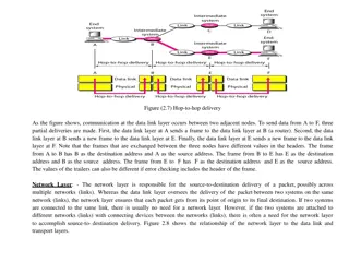
HDLC Control field:
Data link layer is highly responsible for hop to hop delivery
I- FRAME
I-FRAME
N(S) N(R)
S-FRAME
CODE N(R)
U-FRAME
CODE
CODE
•
POLL/FINAL:
P/F=1 poll or final
Poll if frame is send by the primary
Final if frame is sent by the secondary
INFORMATION:
User data in an I-frame
Missing in an S-frame
Management information in a U-frame
primary
secondary
•
S-FRAMES
CODE N(R)
Code command
00 RR-receiver ready
01 REJ-reject
10
RNR-receiver not ready
11 SRE-selective reject
•
RECEIVER READY (RR):
Positive ack of received I-frame
•
RECEIVER NON-READY (RNR):
Is RR frame with additional duties
It ack the receipt of a frame that the receiver is busy
•
REJECT (REJ):
This is a NAK frame that can be used in go-back-N
•
SELECTIVE REJECT (SREJ):
This is a NAK frame used in selective repeat ARQ
•
U-FRAMES:
EG: 11 010 – disconnect connection
MAC sublayer:
•
Is sublayer in which channel is allocation to multiple user
•
MAC sublayer is important in LANS
CHANNEL ALLOCATION PROBLEM:
In which a single channel is divided allotted to multiple user is
order to carry a user specific tasks
DYNAMIC CHANNEL ALLOCATION
It is based up on possible
•
Station model
•
Single channel assumption
•
Collision assumption
•
Time
Continuous
Slotted
•
Carrier sense
•
No carrier sense
STATION MODEL:
•
Model consists of N independent stations (Eg: computer,
telephone or personal communication ) each with a program
•
Stations are sometime called terminates
•
A frame being generated in an interval of length t is
lamda t
•
Where lamda is a constant create of new frame
•
One frame is generated, station is blocked and does nothing until
the frame has be successfully transmitted
SINSLE CHANNEL ASSUMPTION
•
Single channel is available for all communication
•
All stations can transmit on it and all can receive from it
COLLISION ASSUMPTION
•
If two frames are transmitted simultaneously, they develop in
time, tjis event is called a collision
•
Collision frame must be transmitted again
TIME:
It can be divided into two types
1.
Continuous time
2.
Slotted time
•
CONTINUOUS TIME:
frame transmission can begin at any instant. There is no
matter clock dividing time into discrete intervals
•
SLOTTED TIME:
Time is divided into discrete intervals (slots). Frame
transmissions always begin at the start of a slot.
CARRIER SENSE
If the channel is in use before trying to use it, if the channel is
busy no station will be use
NO CARRIER SENSE
Stations cannot sense the channel before trying to use it. Time
of used to sense loss data.
The Data Link Layer (DLL) is the second layer of the OSI model, responsible for error detection and correction, framing, addressing, synchronization, flow control, and multi-access protocols. It deals with logical link control and media access control, addressing destination hardware, avoiding data loss, and managing data transmission speed. DLL ensures secure and efficient communication between network devices by encapsulating data into frames and providing mechanisms for error detection and correction. Explore the functionalities and design issues associated with the DLL to enhance your understanding of network communication protocols.

Download Presentation

Please find below an Image/Link to download the presentation.
The content on the website is provided AS IS for your information and personal use only. It may not be sold, licensed, or shared on other websites without obtaining consent from the author. Download presentation by click this link. If you encounter any issues during the download, it is possible that the publisher has removed the file from their server.
E N D
Presentation Transcript
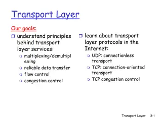
DESIGN ISSUSES: Error detection and correction Stop and wait protocol Sliding window protocols Eg : data link protocols THE MAC SUB LAYER: The channel allocation problem Multiple access protocols Wireless LANS-bridges-FDDI
DESIGN ISSUES .Second layer of OSI model .Most complicated layer and has complex functionalites
DLL IS DIVIDED INTO 2 SUBLAYERS Logical link control: It deal with protocols, flows, error controls Media access control: It deal with actual control of media
FUNCTIONALITY OF DATA LINK LAYER Farming Addressing Synchronization Error control Flow control Multi access
FRAMING: It takes packets from internet layer and encapsulates them into frames It sends each frame bit by bit to receiver. ADDRESSING: DLL provides addressing destination hardware address will be included in header
SYNCHRONIZATION: To avoid data loose sending some check point and if any data is lost will not go with the first frame and continue with the same frame where error is occur ERROR CONTROL: It can occur during transmission that can be detect in data link layer. Receiver sends acknowledgement to transmit the corrupted data
FLOW CONTROL: When a data frame is send from one host to other over a single medium, it is required that a sender and receiver should at a same speed It sender is sending to fast the receiver may be over loaded MULTIACCESS: Multiple user can access a shared media among multiple system
ERROR DETECTION AND CORRECTION There are many mesons such as noise, cross-talk etc. which may help data to get corrupted during transmission. DLL uses some error control mechanism. To understand how errors is controlled, it is essential to known what types of errors may occur.
TYPES OF ERROR THREE TYPES OF ERRORS Single bit error Multiple bit error Burst error
SINGLE BIT ERROR: 0 1 1 1 0 0 1 1 0 1 1 1 0 1 1 1 sent received In a frame, there is only one bit, anywhere through, which is corrupt. MULTIPLE BIT ERROR: 1 0 1 1 0 0 1 1 1 0 1 0 0 1 1 1 sent received Frame is received with more than one bits in corrupted state
BURST ERROR: 1 0 1 1 0 0 1 1 1 1 0 0 0 1 1 1 sent received Frame contains more than or consecutive bits corrupted Error control mechanism may involve two possible ways Error detection Error correction
ERROR DETECTION Errors in the received frames are detected by means of Parity check Cyclic redundancy check Check sum
PARITY CHECK: One extra bit is sent along with the original bits to make number of is either even in case of even parity or odd in case of odd parity. Count of is should be even 1 0 1 0 0 101000 101000 sender data even parity bit receiver This is even parity. The no. 1 is in odd
Odd parity: 10101 101001 101011 Sender data odd parity The no. of 1 is in even. Multiple error bits are not rectified by parity check
CYCLIC REDUNDANCY CHECK Data 1 0 1 1 0 1 CRC generator 1 1 0 1 CRC bits = n-1 =3
CHECK SUM: In check sum error detection scheme, the data is divided into k segments each of m bits In the gender s end the segments are added using 1 s complement arithmetic to get the sum. The sum is complemented to get check sum The check sum segment is sent along with the data segments At the receivers end, all received segments are added using is complement arithmetic to get the sum. The sum is complemented
If the result is zero the received data is accepted, other wise discarded original data
ERROR CORRECTION TECHNIQUES: Error correction techniques find out the exact number of bits that have been corrupted and as well as their locations. Two principle ways Backward error correction (retransmission) Forward error correction
BACKWARD ERROR: Receiver detects an error in the incoming frame, it requests the sender to retransmit the frame Retransmitting is not expensive as in fiber optics. FORWARD ERROR CORRECTION: Receiver detects some error in the incoming frame, it executes error correction code that generates the actual frame It there are too many errors, the frames need to be retransmitted. The two main error correction codes are 1.Hamming codes 2. binary convolution code
STOP AND WAIT Two types of mechanism can be implemented to the control the flow This flow control mechanism forces the sender after transmitting a data frame to stop and wait until the acknowledgement of the data frame send is received.
REQUIREMENTS FOR ERROR CONTROL MECHANISM Error detection Positive ack Negative ack Retransmission
ERROR DETECTION: The sender and receiver, either both or any, must know that there is some error in transit. POSTIVE ACK: When the receiver receives the correct frame, it should acknowledgement it NEGATIVE ACK: When the receiver receives a damage frame or duplicate frame, It send a NACK. Back to the sender and the sender must retransmit the correct frame.
RETRANSMISSION: The sender maintains a clock and sets a time out period It may acknowledgement of a data frame previously transmitted does not arrive before the time out the sender retransmit the frame, thinking the frame or it s acknowledgement is lost in transit
There are three types of techniques available in DLL Stop and wait (ARQ-Automatic repeat request)- go-back-N ARQ Selective repeat ARQ
SLIDING WINDOW: In this flow control mechanism both sender and receiver agree on the number of data frames after which the acknowledgement should be sent stop and wait flow control mechanism. Wastes resource this protocol tries to make use of underlying resource as much as possible. 1. go-back-N 2. Selective repeat Send multiple frames at a time No of frames to be send is based on window sizes Each frame is number sequences number.
Go-back-N ARQ: Stop and wait ARQ mechanism does not utilize the resources at there best. When the acknowledgement is received the sender sits ideal and does nothing, in go-back-N ARQ method, both sender and receiver maintain the window
The sending window size enables the sender to send multiple frames without receiving the acknowledgement of the previous one. The receiving window enable the receiver to receive multiple frames and acknowledge them. The receiver keeps track of incoming frames in sequences number. When the sender sends all the frames in window, it checks up to what s sequences number it has receive positive acknowledgement. If all frames are positively acknowledged, the sender sends next set of frames. If sender finds that it has received NACK or has not receive any ack for a particular frame, it retransmits all the frames after to which does not receive any positive ack.
SELECTIVE REPEAT ARQ: In Go-back-N ARQ, it is assumed that the receiver does not have any buffer space for it s window. Size and has to process each frame as it comes. This enforces the sender to retransmit All the frames which are not acknowledged In selective repeat ARQ, there is receiver by keeping track of sequences number, buffer. The frame in memory and send NACK for only framed which is missing or damaged
The sender in this case sends only packet for which NACK is received.
Example data link protocols: 1. HDLC [High level data link control] 2. The data link layer in the internet HDLC : Derived from SDLC used in IBM Main framing [Synchronous Data link protocols] Bit oriented protocol used bit stuffing Reliable protocol / selective repeat or go-back-N Full duplex communication There are three different classes or Frames used in HDLC Information frames: which carry actual information such frames can piggy back Ack.
Supervisory frames: Which are used for error and flow control purpose and hence contain send and sequence numbers Unnumbered frames: Used in link set up and disconnection HDLC Frames types: 1. Information frames 2. Supervisory frames 3. Unnumbered frames
FLAG ADDRESS CONTROL USER INFROMATION FCS FLAG INFORMATION FRAME FLAG ADDRESS CONTROL FCS FLAG SUPERVISORY FRAME FLAG ADDRESS CONTROL MANAGEMENT INFORMATION FCS FLAG UNNUMBERED FRAME
FLAG FIELD: Is 8bits of a fixed pattern (01111110) There is one flag at the beginning and one at the end frame The ending flag of one frame can be used as the beginning flag of the next frame To guarantee that the flag does not appear any where else in the frame HDLC uses a process called bit suffing BITS 8 8 8 >0 16 8 01111110 ADDRESS CONTROL DATA CHECKSUM 01111110
HDLC Control field: Data link layer is highly responsible for hop to hop delivery I- FRAME FLAG ADDRESS CONTROL INFORMATION FCS FLAG I-FRAME 0 PF N(S) N(R) 0 1 PF S-FRAME CODE N(R) U-FRAME 1 1 PF CODE CODE
POLL/FINAL: P/F=1 poll or final Poll if frame is send by the primary Final if frame is sent by the secondary primary secondary INFORMATION: User data in an I-frame Missing in an S-frame Management information in a U-frame
S-FRAMES FLAG ADDRESS FCS FLAG CONTROL 1 0 PF CODE N(R) Code command 00 RR-receiver ready 01 REJ-reject 10 RNR-receiver not ready 11 SRE-selective reject
RECEIVER READY (RR): Positive ack of received I-frame RECEIVER NON-READY (RNR): Is RR frame with additional duties It ack the receipt of a frame that the receiver is busy REJECT (REJ): This is a NAK frame that can be used in go-back-N SELECTIVE REJECT (SREJ): This is a NAK frame used in selective repeat ARQ
U-FRAMES: FLAG ADDRESS CONTROL MANAGEMENT FCS FLAG INFORMATION 1 1 PF EG: 11 010 disconnect connection
MAC sublayer: Is sublayer in which channel is allocation to multiple user MAC sublayer is important in LANS CHANNEL ALLOCATION PROBLEM: In which a single channel is divided allotted to multiple user is order to carry a user specific tasks
STATIC CHANNEL ALLOCATION: It is a traditional approach of allocating a single channel among multiple users by FDM If these are N users, the bandwidth PS divided into N equal sized portions each user being assigned one portion. Difference between no interface and user T= ??+? 1 T=Time delay C=capacity of channel ? = ??????? ???? ?? ?????? ? = ???? ??? ??????
DYNAMIC CHANNEL ALLOCATION It is based up on possible Station model Single channel assumption Collision assumption Time Continuous Slotted Carrier sense No carrier sense
STATION MODEL: Model consists of N independent stations (Eg: computer, telephone or personal communication ) each with a program Stations are sometime called terminates A frame being generated in an interval of length t is lamda t Where lamda is a constant create of new frame One frame is generated, station is blocked and does nothing until the frame has be successfully transmitted
SINSLE CHANNEL ASSUMPTION Single channel is available for all communication All stations can transmit on it and all can receive from it COLLISION ASSUMPTION If two frames are transmitted simultaneously, they develop in time, tjis event is called a collision Collision frame must be transmitted again
TIME: It can be divided into two types 1. Continuous time 2. Slotted time CONTINUOUS TIME: frame transmission can begin at any instant. There is no matter clock dividing time into discrete intervals SLOTTED TIME: Time is divided into discrete intervals (slots). Frame transmissions always begin at the start of a slot.
CARRIER SENSE If the channel is in use before trying to use it, if the channel is busy no station will be use NO CARRIER SENSE Stations cannot sense the channel before trying to use it. Time of used to sense loss data.


:")