Understanding Data Link Layer in Computer Networking
Explore the important concepts of the Data Link Layer including Ethernet addresses, Media Access Control (MAC), Controlled Access, and Contention. Learn how these elements control the transmission of data in computer networks and impact network performance based on traffic conditions.

Download Presentation

Please find below an Image/Link to download the presentation.
The content on the website is provided AS IS for your information and personal use only. It may not be sold, licensed, or shared on other websites without obtaining consent from the author. Download presentation by click this link. If you encounter any issues during the download, it is possible that the publisher has removed the file from their server.
E N D
Presentation Transcript
Chapter 4 Data Link Layer
INFORMATION SYSTEMS ASSOCIATION ISA Club Meeting January 26, 2017 6:00pm CI 1006 Come grab free pizza and help us brainstorm upcoming events and the future direction of ISA
Announcements and Outline Recap Physical Layer Circuits Media Digital Transmission (Digital Data) Analog Transmission (Digital Data) Digital Transmission (Analog Data) Outline Data Link Layer Media Access Control Error Control Data Link Protocols 3
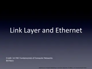
Network Layers Computer 1 Computer 2 4
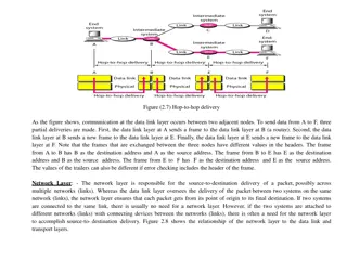
Data Link Layer - Introduction Responsible for moving messages from one device to another Network Layer Data Link Layer Controls the way messages are sent on media Physical Layer Organizes physical layer bit streams into coherent messages for the network layer Major functions of a data link layer protocol Media Access Control Error Control Message Delineation 5
Media Access Control (MAC) Controlling when and what computer transmit Why used: When to use: Two possible approaches Controlled access Contention based access 7
Controlled Access Controlling access to shared resources Commonly used by mainframes (or its front end processor) Also used by some LAN protocols 8
Contention Collisions ? Common Use: Problematic? 9
Relative Performance Depends on network conditions With high traffic, _________ access is better because of the high collisions of __________. With low traffic, the higher overhead of _________ access makes __________ more efficient. Cross-over point Cross-over point used to be 20 devices, but very much depends on devices, protocols, traffic, etc. 10
Error Control Handling of network errors caused by problems in transmission Network errors Human errors Categories of Network Errors Corrupted Lost data 11
Error Control (Cont.) Error Rate Burst Error 12
Sources of Errors Line noise and distortion major cause More likely on electrical media Undesirable electrical signal Introduced by equipment and natural disturbances Degrades performance of a circuit Manifestation Extra bits Flipped bits Missing bits 13
Sources of Errors 1. White Noise 2. Impulse Noise 14
Sources of Errors 3. Cross Talk 4. Echo 15
Sources of Errors Source Examples What do you think is a major cause of impulse noise? 16
Sources of Errors and Prevention What causes it How to prevent it Source of Error Faulty equipment, Storms, Accidents (circuit fails) Movement of electrons (thermal energy) Sudden increases in electricity (e.g., lightning, power surges) Multiplexer guard bands are too small or wires too close together Poor connections (causing signal to be reflected back to the source) Gradual decrease in signal over distance (weakening of a signal) Signals from several circuits combine Analog signals change (small changes in amp., freq., and phase) Amplifier changes phase (does not correctly amplify its input signal) Line Outages Increase signal strength (increase SNR) Shield or move the wires White Noise More important Impulse Noise Increase the guard bands, or move or shield the wires Fix the connections, or tune equipment Use repeaters or amplifiers Cross-talk Echo Attenuation mostly on analog Move or shield the wires Intermodulation Noise Jitter Tune equipment Tune equipment Harmonic Distortion 17
Major Functions of Error Control Error prevention Error detection Parity checks Cyclic Redundancy Check (CRC) Error correction 18
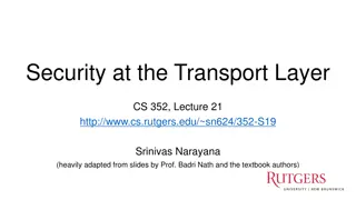
Error Detection Sender calculates an Error Detection Value (EDV) and transmits it along with data Receiver recalculates EDV and checks it against the received EDV Mathematical calculations Mathematical calculations DATA EDV DATA DATA EDV ? = EDV EDV 19
Error Detection Techniques 1. Parity checks 2. Cyclic Redundancy Check (CRC) 20
Parity Checking One of the oldest and simplest A single bit added to each character Even parity: Odd parity: Receiving end recalculates parity bit If one bit has been transmitted in error the received parity bit will differ from the recalculated one 21
Examples of Using Parity Sending the letter A (01100010) using odd parity bit sender receiver 22
Cyclic Redundancy Check (CRC) Treats entire message as a number, divides by a preset number and uses the remainder as the check code in the message Preset number is chosen by sender and receiver to ensure that the remainder is no longer than 16 or 32 bits depending on detection mode. Detection modes: CRC-16 CRC-32 23
Error Correction Once detected, the error must be corrected Error correction techniques Retransmission (or, backward error correction) Forward Error Correction 24


")


")


")