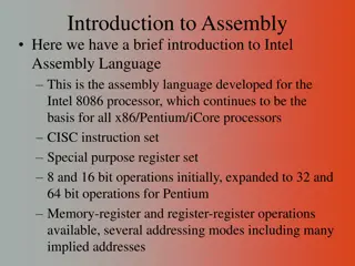
Understanding Assembly Language and 8086 Microprocessors
Dive into the world of Assembly Language, data representation, and 8086 microprocessors. Explore topics like memory organization, integer representation, and computer registers. Learn about the structure and functionality of machine language instructions, as well as the convenience of using assembly language for programming tasks.

Download Presentation

Please find below an Image/Link to download the presentation.
The content on the website is provided AS IS for your information and personal use only. It may not be sold, licensed, or shared on other websites without obtaining consent from the author. Download presentation by click this link. If you encounter any issues during the download, it is possible that the publisher has removed the file from their server.
E N D
Presentation Transcript
Assembly Language Part I Data Representation and 8086 Microprocessors Department of Computer Science, Faculty of Science, Chiang Mai University
Outline Data Organization Programming Languages Integer Representation Character Representation Organization of the 8086/8088 Microprocessors Computer Registers 2 204231: Computer Organization and Architecture
Memory Represented as Bytes 3 204231: Computer Organization and Architecture
Bit - Byte - Word Information processed by the computer is stored in its memory. The memory circuits are usually organized into groups that can store eight bits of data. A string of eight bits is called a byte. Each memory byte is identified by a number that is called address. The data stored in a memory byte are called its contents. 4 204231: Computer Organization and Architecture
Bit Position The positions are numbered from right to left, starting with 0. In a word, the bits 0 to 7 form the low byte and the bits 8 to 15 form the high byte. For a word stored in memory, its low byte comes from the memory byte with the lower address and its high byte is from the memory byte with the higher address. 5 204231: Computer Organization and Architecture
Bit Positions in a Byte and a Word 6 204231: Computer Organization and Architecture
Machine Language The CPU can only execute machine language instructions. They are bit strings. The Opcode specifies the type of operation. The Operands are often given as memory addresses to the data to be operated on. 00000101 00000100 00000000 ; Add 4 to AX. 7 204231: Computer Organization and Architecture
Assembly Language A more convenient language to use We use symbolic names to represent operations, registers, and memory locations. Assembler ADD AX, 4 8 204231: Computer Organization and Architecture
Integer Representation The Least Significant Bit (LSB) is the rightmost bit. In a byte or word, bit 0 The Most Significant Bit (MSB) is the leftmost bit. In a word, bit 15 In a byte, bit 7 9 204231: Computer Organization and Architecture
Unsigned Integers An unsigned integer represents a magnitude. Unsigned integers are appropriate for representing quantities that can never be negative. Addresses of memory locations Counters ASCII Code 10 204231: Computer Organization and Architecture
Unsigned Integers The largest unsigned that can be stored in a byte is 1111 1111= FFh = 255. The biggest unsigned integer a 16-bit word can hold is 1111 1111 1111 1111 = FFFFh =65535. Note that if the least significant bit of an integer is 1, the number is odd, and it s even if the lsb is 0. 11 204231: Computer Organization and Architecture
Signed Integers A signed integer can be positive or negative. The msb is reserved for the sign: 1 means negative. 0 means positive. Negative integers are stored in the computer in a special way known as two s complement. 12 204231: Computer Organization and Architecture
Twos Complement The one s complement of an integer is obtained by complementing each bit; that is, replace each 0 by a 1 and each 1 by a 0. To get the two s complement of an integer, just add 1 to its one s complement. 13 204231: Computer Organization and Architecture
Find the twos complement of 5. 5 = 0000 000000000101 One s com. of 5 = 1111 1111 1111 1010 Two s com. of 5 = 1111 1111 1111 1011 14 204231: Computer Organization and Architecture
Subtraction as Twos Complement Addition A subtraction can be done by bit complementation and addition. The circuits that add and complement bits are easy to design. 15 204231: Computer Organization and Architecture
Subtraction as Twos Complement Addition Ex.: Suppose AX contains 5ABCh and BX contains 21FCh. Find the difference of AX minus BX by using complementation and addition. Solution: 5ABCh = 0101 1010 1011 1100 + One s com. of 21FCh = 1101 1110 0000 0011 +1 Difference = 1 0011 1000 1100 0000 = 38C0h Note that 21FCh = 0010 0001 1111 1100 16 204231: Computer Organization and Architecture
Subtraction as Twos Complement Addition A one is carried out of the most significant bit and is lost. The answer stored, 38C0h, is correct, as may be verified by hex subtraction. 17 204231: Computer Organization and Architecture
Unsigned Decimal Interpretation Just do a binary-to-decimal conversion. It s usually easier to convert binary to hex first, and then convert hex to decimal. 18 204231: Computer Organization and Architecture
Signed Decimal Interpretation If the msb is 0, the number is positive, and the signed decimal is the same as the unsigned decimal. If the msb is 1, the number is negative, so call it N. To find N, just take the two s complement and then convert to decimal as before. 19 204231: Computer Organization and Architecture
Suppose AX contains FE0Ch. Give the unsigned and signed decimal interpretations. FE0Ch = 1111 1110 0000 1100 For the unsigned decimal interpretations FE0Ch = 65036 For the signed decimal interpretations FE0Ch = N One s com. of FE0Ch = 0000 0001 1111 0011 Two s com. of FE0Ch = 0000 0001 1111 0100 N = 01F4h = 500 20 204231: Computer Organization and Architecture
ASCII Code American Standard Code for Information Interchange Code The ASCII Code system uses seven bits to code each character, so there are a total of 27= 128 ASCII codes. Notice that only 95 ASCII codes, from 32 to 126, are considered to be printable. 21 204231: Computer Organization and Architecture
Show how the character string RG 2z is stored in memory, starting at address 0. Address 0 1 2 3 4 Contents 0101 0010 0100 0111 0010 0000 0011 0010 0111 1010 Character R G 2 z 22 204231: Computer Organization and Architecture
The 8086 and 8088 Microprocessors Intel introduced the 8086 in 1978 as its first 16-bit microprocessor. A 16-bit processor can operate on 16 bits of data at a time. The 8088 has an 8-bit data bus. Because the 8086 and 8088 essentially have the same internal structure, the name 8086 applies to both 8086 and 8088. 23 204231: Computer Organization and Architecture
8086 Registers AX: Accumulator Register BX: Base Register CX: Count Register DX: Data Register CS: Code Segment DS: Data Segment SS: Stack Segment ES: Extra Segment SI: Source Index DI: Destination Index SP: Stack Pointer BP: Base Pointer IP: Instruction Pointer 24 204231: Computer Organization and Architecture
Data Registers General-Purpose Registers Data registers are available to programmers for general data manipulation. Even though a processor can operate on data stored in memory, the same instruction is faster (requires fewer clock cycles) if the data are stored in registers. The high and low bytes of data registers can be accessed separately. 25 204231: Computer Organization and Architecture
Segment Registers Address Registers Segment registers store addresses of instructions and data in memory. These values are used by a processor to access memory location. The idea of memory segments is a direct consequence of using a 20-bit address in a 16-bit processor. 26 204231: Computer Organization and Architecture
Segment Registers 27 204231: Computer Organization and Architecture
Physical Address 8086 assigns a 20-bit physical address to its memory. It is possible to address 220= 1,048,576 bytes (one megabyte) of memory. 28 204231: Computer Organization and Architecture
Physical Address 0000 0000 0000 0000 0000 0000 0000 0000 0000 0001 0000 0000 0000 0000 0010 0000 0000 0000 0000 0011 1111 1111 1111 1111 1110 1111 1111 1111 1111 1111 00000h 00001h 00002h 00003h FFFFEh FFFFFh 29 204231: Computer Organization and Architecture
Segment A memory segment is a block of 216(or 64 K) consecutive memory bytes. Each segment is identified by a segment number, starting with 0. A segment number is 16 bits, so the highest segment number is FFFFh. 30 204231: Computer Organization and Architecture
Offset Within a segment, a memory location is specified by giving an offset. An offset is the number of bytes from the beginning of the segment. With a 64-KB segment, the offset can be given as a 16-bit number. The first byte in a segment has offset 0. The last offset in a segment is FFFFh. 31 204231: Computer Organization and Architecture
Logical Address Segment:Offset Addressing To obtain a 20-bit physical address, the 8086 microprocessors first shifts the segment address 4 bits to the left (this is equivalent to multiplying by 10h), and then adds the offset. Physical Address = Segment 10h + Offset A4FB:4872 = A4FB0h + 4872h = A9822h 32 204231: Computer Organization and Architecture
Pointer and Index Registers SP, BP, SI, and DI normally point to (contain the offset addresses of) memory locations. Unlike segment registers, pointer and index registers can be used in arithmetic and other operations. 33 204231: Computer Organization and Architecture
IP (Instruction Pointer) To access instructions, 8086 uses CS and IP. CS contains the segment number of the next instruction, and IP contains the offset. IP is updated each time an instruction is executed so that it will point to the next instruction. Unlike other registers, IP cannot be directly manipulated by an instruction; that is, an instruction may not contain IP as its operand. 34 204231: Computer Organization and Architecture
FLAGS Register The purpose of FLAGS is to indicate the status of a microprocessor When a subtraction operation results in a 0, ZF (zero flag) is set to 1 (true). 35 204231: Computer Organization and Architecture
Reference Ytha Yu and Charles Marut, Assembly Language Programming and Organization of the IBM PC. New York: McGraw-Hill, 1992. 36 204231: Computer Organization and Architecture


")