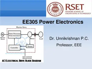
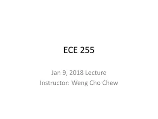
Fundamentals of Circuits and Electronics

Pre-Intro to Circuits and
Electronics
Prepared by: Dayton Huffaker, Jasen Nicolas, Cyrus Khaleeli
Table of Contents
•
Intro to circuits
•
How to measure circuit properties
•
Large vs. Small signal
•
Basics of Diodes, BJTs, MOSFETS
•
Intuitive understanding of coding in
Arduino IDE
•
Magnetism
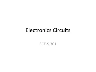
What is electricity?
Water in a Pipe
Electricity
Pump
ΔP=12psi
Q=3gpm
Orifice
ΔP=12psi
Q=3gpm
Voltage Source
ΔV=12 Volts
I=3 Amps
Resistor
ΔV=12 Volts
I=3 Amps
We can think of Voltage and
Pressure as equivalents, Current
and Flow as equivalents, and line
resistance devices as equivalents
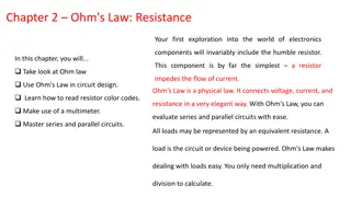
Circuit Analysis Techniques
Kirchhoff’s Voltage Law (KVL)
•
The sum of the individual
voltage differences in a loop
are equal to zero
•
Can think of it like an energy
balance equation. What
comes in must go out
KVL Example
I
1
R
1
v
D
v
1
How to Measure Circuit Properties
How to Measure
Circuit
Properties
•
Current Measurement:
•
Connect in series
with the circuit
How to Measure
Circuit
Properties
•
Current Measurement:
•
Connect in series
with the circuit
How to Measure
Circuit Properties
•
Voltage Measurement:
•
Connect in parallel with the circuit
•
Red (positive) lead connects to
point of higher potential
•
Black (negative) lead connects to
point of lower potential
•
It is important to remember that
the measured voltage is relative to
the black (negative) lead
Large vs. Small Signal
•
DC and AC signals with fancy wording.
•
Large signal = DC
•
Subscripts are capitalized ex: i
D
, v
BE
•
Small signal = AC
•
Subscripts are lowercase ex: i
c
, v
in
•
Can have a power source that has both large and small signal
components
•
When solving these problems, you separate the two
Large Signal
•
Voltage stays at a constant 10V
throughout the time period
Voltage
Time
Large and Small Signal
•
Voltage average is 10V, but “wiggles”
around it due to the 2VAC source
•
Notice that it changes by 2V in both
directions from 10V (8V to 12V)
Voltage
Time
Component Reactions:
Large Signal
Capacitor: “Open circuit.” No change
in voltage to create a current
Inductor: “Short circuit.” No change in
current to create a voltage
Component Reactions:
Small Signal
Use complex circuit analysis
techniques to solve for these. V=IZ.
Remember that:
Z
R
= R
Z
C
= 1/(j
ω
C)
Z
L
=j
ω
L
Some components have specific
small-signal equivalents
Diodes
•
Allows current to flow in one direction.
•
Fluids analogy: Think of a check valve!
•
Zener Diode: has a set voltage at which
point current can flow in the other
direction, known as
the breakdown region
Bipolar Junction
Transistors (BJT)
•
Can think of it like a current
controlled switch
•
The amount of current you put
into the (B)ASE is proportional to
the amount that you achieve
from the (C)OLLECTOR to the
(E)MITTER
•
Fluids analogy: acts like an
eductor (remember the venturi
effect?)
BJTs continued
Important equations:
•
ie=ib+ic
•
ic=ϐib
•
ϐ is a scale factor for your collector current
•
npn is “normally-open”
•
pnp is “normally-closed”
Relatively small input i
b
i
c
i
e
Field Effect Transistors
(FET)
•
Voltage controlled switch
•
Supply a predetermined voltage
to the (G)ATE to “close” or “turn
on” the switch between the
(D)RAIN and (S)OURCE
•
Think of it like a switch but
instead of using your hand you
use a voltage
Important MOSFET Notes
Saturation Region Drain Current:
Intuitive Understanding of Coding in Arduino IDE
•
Code controls various input and output devices
Basic Code Organization as an Example: Going on a Run
Define initial properties here!
Ex: Tie your shoes and stretch.
Basic Code Organization as an Example: Going on a Run
Define initial properties here!
Ex: Tie your shoes and stretch.
Basic Code Organization as an Example: Going on a Run
Repeated operations go here!
Ex: Take a step forward.
After reaching the “},” it will return to void loop(); and
start again line-by-line in the same order.
Example Code: Blink
Delve into the foundational concepts of circuits and electronics through an engaging exploration of voltage, current, resistance, and circuit analysis techniques like Kirchhoff's laws. Learn how to measure circuit properties effectively in this introductory guide.

Download Presentation

Please find below an Image/Link to download the presentation.
The content on the website is provided AS IS for your information and personal use only. It may not be sold, licensed, or shared on other websites without obtaining consent from the author. Download presentation by click this link. If you encounter any issues during the download, it is possible that the publisher has removed the file from their server.
E N D
Presentation Transcript
Pre-Intro to Circuits and Electronics Prepared by: Dayton Huffaker, Jasen Nicolas, Cyrus Khaleeli
Table of Contents Intro to circuits How to measure circuit properties Large vs. Small signal Basics of Diodes, BJTs, MOSFETS Intuitive understanding of coding in Arduino IDE Magnetism
We can think of Voltage and Pressure as equivalents, Current and Flow as equivalents, and line resistance devices as equivalents What is electricity? Water in a Pipe Electricity Voltage Source V=12 Volts I=3 Amps Pump P=12psi Q=3gpm Resistor V=12 Volts I=3 Amps Orifice P=12psi Q=3gpm
Circuit Analysis Techniques Kirchhoff s Voltage Law (KVL) Kirchhoff s Current Law (KCL) Nodal Analysis fan favorite Superposition Loop/Mesh
Kirchhoffs Voltage Law (KVL) The sum of the individual voltage differences in a loop are equal to zero Can think of it like an energy balance equation. What comes in must go out ? = 0
KVL Example I1R1 v1 vD 0 = +?1 ?1?1 ?? ?? 0 = ?1+ ?1?1+ ??
How to Measure Circuit Properties Current Measurement: Connect in series with the circuit
How to Measure Circuit Properties Current Measurement: Connect in series with the circuit
How to Measure Circuit Properties Voltage Measurement: Connect in parallel with the circuit Red (positive) lead connects to point of higher potential Black (negative) lead connects to point of lower potential It is important to remember that the measured voltage is relative to the black (negative) lead
Large vs. Small Signal DC and AC signals with fancy wording. Large signal = DC Subscripts are capitalized ex: iD, vBE Small signal = AC Subscripts are lowercase ex: ic, vin Can have a power source that has both large and small signal components When solving these problems, you separate the two
Voltage Large Signal Voltage stays at a constant 10V throughout the time period Time
Voltage Large and Small Signal Voltage average is 10V, but wiggles around it due to the 2VAC source Notice that it changes by 2V in both directions from 10V (8V to 12V) Time
Component Reactions: Large Signal Capacitor: Open circuit. No change in voltage to create a current Inductor: Short circuit. No change in current to create a voltage
Component Reactions: Small Signal Use complex circuit analysis techniques to solve for these. V=IZ. Remember that: ZR = R ZC= 1/(j C) ZL=j L Some components have specific small-signal equivalents
Diodes Allows current to flow in one direction. Fluids analogy: Think of a check valve! Zener Diode: has a set voltage at which point current can flow in the other direction, known as the breakdown region
Bipolar Junction Transistors (BJT) Can think of it like a current controlled switch The amount of current you put into the (B)ASE is proportional to the amount that you achieve from the (C)OLLECTOR to the (E)MITTER Fluids analogy: acts like an eductor (remember the venturi effect?)
BJTs continued Important equations: ie=ib+ic ic= ib is a scale factor for your collector current npn is normally-open pnp is normally-closed ic Relatively small input ib ie
Field Effect Transistors (FET) Voltage controlled switch Supply a predetermined voltage to the (G)ATE to close or turn on the switch between the (D)RAIN and (S)OURCE Think of it like a switch but instead of using your hand you use a voltage
??? ???
Important MOSFET Notes Saturation Region Drain Current: Very likely to see saturation region: PMOS is like a normally-closed switch ??? ???, ??? ??? ??? NMOS is like a normally-open switch ??? ???, ??? ??? ??? Other regions have different characteristics Current to the Gate is always zero. 2 ??= ? ??? ???
Intuitive Understanding of Coding in Arduino IDE Code controls various input and output devices
Basic Code Organization as an Example: Going on a Run Define initial properties here! Ex: Tie your shoes and stretch.
Basic Code Organization as an Example: Going on a Run Define initial properties here! Ex: Tie your shoes and stretch. Repeated operations go here! Ex: Take a step forward. After reaching the }, it will return to void loop(); and start again line-by-line in the same order.


")