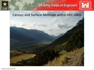
Visible Surface Detection in Computer Graphics
Understanding the importance of Visible Surface Detection (VSD) in computer graphics, focusing on techniques like backface culling and the Depth-Buffer Method to determine visible surfaces in a scene. Limitations of back-face culling and the Depth-Buffer Algorithm are addressed along with practical examples and illustrations.

Download Presentation

Please find below an Image/Link to download the presentation.
The content on the website is provided AS IS for your information and personal use only. It may not be sold, licensed, or shared on other websites without obtaining consent from the author. Download presentation by click this link. If you encounter any issues during the download, it is possible that the publisher has removed the file from their server.
E N D
Presentation Transcript
CS552: Computer Graphics Lecture 30: Visible Surface Detection
Recap Solid Modeling o Represent the solid object in a 3D space o B-Reps o Subdividing algorithms
Objective After completing this lecture, students will be able to o Explain the importance of VSDs o Solve the problem of backface culling
Visible Surface Detection A surface normal vector N and the viewing-direction vector Vview. A polygon surface with plane parameter C< 0 in a right-handed viewing coordinate system is identified as a back face when the viewing direction is along the negative
Limitation of Back-face Culling Concave polyhedron with one face partially hidden by other faces of the object.
Depth-Buffer Method Image-space approach for detecting visible surfaces Compares surface depth values throughout a scene for each pixel position on the projection plane Each surface of a scene is processed separately\ The algorithm is usually applied to scenes containing only polygon surfaces Also frequently alluded to as the z-buffer method
Illustration Three surfaces overlapping pixel position ( ?,? ) on the view plane. The visible surface, ?1, has the smallest depth value.
Depth-Buffer Algorithm 1. Initialize the depth buffer and frame buffer so that for all buffer positions (x, y), 1. depthBuff (x, y) = 1.0, frameBuff (x, y) = backgndColor 2. Process each polygon in a scene, one at a time, as follows: 1. For each projected (x, y) pixel position of a polygon, calculate the depth z (if not already known). 2. If z < depthBuff (x, y), compute the surface color at that position and set 3. depthBuff (x, y) = z, frameBuff (x, y) = surfColor (x, y) After all surfaces have been processed, the depth buffer contains depth values for the visible surfaces and the frame buffer contains the corresponding color values for those surfaces
Calculation Given the depth values for the vertex positions of any polygon in a scene At surface position (x, y), the depth is calculated from the plane equation as: ? = ?? ?? ? ? The depth z of the next position (x+1, y) along the scan line is obtained ? = ?(? + 1) ?? ? ?
Illustration y-1 scan line
A-Buffer Method An extension of the depth-buffer ideas An antialiasing, area-averaging, visibility-detection method REYES ( Renders Everything You Ever Saw ) The buffer region - accumulation buffer Stores a variety of surface data, in addition to depth values
Advantage of A-Buffer Each position in the A-buffer has two fields Depth field: A real-number value (+ve, -ve, 0). Surface data field: Surface data or a pointer.
A buffer: Surface Information RGB intensity components Opacity parameter (percent of transparency) Depth Percent of area coverage Surface identifier Other surface-rendering parameters
Scan-Line Method Image-space method for identifying visible surface Compares depth values along the various scan lines for a scene Different tables used for VSD o Edge table o Surface-facet table o Active list table Flag for each surface
Depth-Sorting Method Uses both image-space and object-space operations Surfaces are sorted in order of decreasing depth Surfaces are scan converted in order, starting with the surface of greatest depth. Sorting operations are carried out in both image and object space The scan conversion of the polygon surfaces is performed in image space. Painter s algorithm
Illustration No depth overlap
Depth test 1. The bounding rectangles (coordinate extents) in the xy directions for the two surfaces do not overlap. 2. Surface S is completely behind the overlapping surface relative to the viewing position. 3. The overlapping surface is completely in front of S relative to the viewing position. 4. The boundary-edge projections of the two surfaces onto the view plane do not overlap.
Test 1 Two surfaces with depth overlap but no overlap in the x direction.
Test 2 and 3 Surface S is completely behind the overlapping surface S Overlapping surface S is completely in front of surface S , but S is not completely behind S
Test 4 Two polygon surfaces with overlapping bounding rectangles in the xy plane.
Use of Sorted List Three surfaces that have been entered into the sorted surface list in the order S, S , S should be reordered as S ,S , S. Surface S extends to a greater depth, but it obscures surface S
BSP-Tree Method BSP tree representation
Thank you Next Lecture: Visible Surface Detection