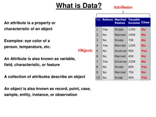
Understanding Attributes and Color Schemes in Graphics
Graphics systems utilize attributes to define how primitives are displayed, such as color and size, while color and grayscale can be stored in different ways like direct storage and indexed storage schemes. The RGB color components play a key role in determining the color shades, with various color parameters and representations used in computer graphics applications.

Download Presentation

Please find below an Image/Link to download the presentation.
The content on the website is provided AS IS for your information and personal use only. It may not be sold, licensed, or shared on other websites without obtaining consent from the author. Download presentation by click this link. If you encounter any issues during the download, it is possible that the publisher has removed the file from their server.
E N D
Presentation Transcript
Attributes of Graphics Systems Attribute parameter: a parameter that affects the way a primitive is to be displayed Attributes may: 1. Determine the fundamental characteristics of a primitive such as color and size. 2. Specify how the primitive is to be displayed under special; conditions such as visibility. 3
Color and Grayscale: RGB color components RGB color can be stored in two ways: - Direct storgse scheme (Frame Buffer) - indexed storage scheme (color tables) 4
Color and Grayscale: Direct storgse scheme Color code placed at pixel location Minimum number of colors for 3-bits Left bit Red, Middle bit Green, Right bit Blue 0 black, 1 blue, , 7 white More color bits increase the size of the frame buffer: 24-bits * 1024 * 1024 = 3MB 5
Color and Grayscale: Direct storgse scheme Minimum of 3 bits of storage per pixel, one bit for each color componenet Requires large storage amount for frame buffer. 6
Color and Grayscale: Indexed storage scheme color lookup tables- colormap: Reduces frame buffer storage 7
Color and Grayscale: Gray scale RGB color functions are used to set shades of gray, or gray scale. When an RGB color setting specifies an equal amount of red, green, and blue, the result is some shade of gray Values close to 0 for the color components produce dark gray, and higher values near 1.0 produce light gray 8
Color and Grayscale: Other Color Parameters Other three-component color representations are useful in computer-graphics applications For example, color output on printers is described with cyan, magenta, and yellow color components (CMY color model) Color interfaces sometimes use parameters such as lightness and darkness to choose a color 9
Color and Grayscale: Color Blending In many applications, it is convenient to be able to combine the colors of overlapping objects or to blend an object with the background Most graphics packages provide methods for producing various color-mixing effects, and these procedures are called color-blending functions or image-compositing functions. 10
Color and Grayscale: Color Blending The RGBA mode is used glutInitDisplayMode(GLUT_SINGLE | GLUT_RGBA); A = alpha coefficient, used to control color blending for overlapping primitives void init ( void) {---- glEnable (GL_BLEND); --- glDisable (GL_BLEND); } 11
Color and Grayscale: Color Blending glClear (GL_COLOR_BUFFER_BIT); //apply clear color to color buffer glBegin(GL_QUADS); // Drawing Using Quads glColor4f(0.0, 1.0, 0.0,0.5); glVertex2i( 80, 10); glVertex2i(120,10); glVertex2i(120,100); glVertex2i(80,100); glColor4f(0.0, 0.0, 1.0,0.5); glVertex2i( 10, 10); glVertex2i(110,10); glVertex2i(110,50); glVertex2i(10,50); glEnd(); // set color to Green // First Quad // set color to blue // Second Quad // finished drawing the Quads 12
Color and Grayscale: Color Blending Without enabling the blending parameter: 13
Color and Grayscale: Color Blending After enabling the blending parameter and setting its value to 0.5: 14
Point Atributes and Functions Two attributes: color and size Color components are set with RGB values or an index into a color table glColor3f(0.0, 1.0, 0.0); // set color to Green glVertex2i( 80, 10); point size is an integer multiple of the pixel size glPointSize (size); // size is the number of pixels glVertex2i(80,10); 15
Line Attributes and Functions Line attributes Basic attributes: color, width, style Width can be set in the line drawing algorithm. Raster algorithms display line attributes by plotting pixel spans, like plotting multiple pixels along the line either horizontally (m<1)or vertically (m>1). Lines are Produced with abrupt ends (horizontal or vertical). Add line caps at the end (butt cap, round cap, projecting square cap). 16
Line Attributes and Functions Line attributes Width Bresenham + additional vertical (horizontal) spans. Width dependent on line slope Line caps Butt round caps square 17
Line Attributes and Functions Line attributes thick polylines with previous method do not connect smoothly miter join: extend the outer boundaries of each segment until they join round join: cap connection with circular boundary bevel join: display line segments with butt caps and fill- in triangular gap between the two butts. 18
Line Attributes and Functions Line attributes Style Solid lines, dashed lines, dotted lines can be generated by modifying the line drawing algorithm spacing between drawn pixels Can be also generated from the raster by using a pixel mask, for example 11111000 will display a dashed line with dash length of 5 and inter-dash length of 3. 19
Line Attributes and Functions Line Width: glLineWidth (width); // width is the width of the line default width is 1.0 Line Style: glLineStipple (repeatFactor, pattern); Requires first: glEnable (GL_LINE_STIPPLE); line-pattern feature can be disabled by glDisable (GL_LINE_STIPPLE); 20
Line Attributes and Functions Line style: pattern references a 16-bit integer that describes how the line should be displayed (default 0xFFFF, all bits set to 1, solid line) repeatFactor specifies how many times each bit in the pattern is to be repeated before the next bit in the pattern in applied (default 1). Example: displays 0x00FF -------- -------- -------- 8 solid line pixels, followed by 8 spaces glLineStipple (repeatFactor, pattern); glLineStipple (1, 0x00FF); 21
Curve Attributes Attributes are the same as for line segments. 22
Character Attributes Character attributes Font (typeface) represent styles Helvetica, Courier, Times Roman, Underlining style solid, dotted, double Style boldface, italics, outline, shadow Size 10-point, 12-point, Color. 23
Character Attributes Bitmap / Raster character: Can be scaled, but not rotated Simple to define Fast to process Bitmap / Raster character: 24
Character Attributes Stroke character: Can be handled like any other object geometric transformations Can be defined once then translated, rotated, and scaled as many times as needed (display lists) Complex to define Take much memory and processing time 25
Character Attributes You have to use glRasterPos to set the raster position before calling glutBitmapString() Note that each call to glutBitmapString() advances the raster position, so several consecutive calls will print out the strings one after another. You can also set the text color by using glColor(). glRasterPos2i(100, 120); glColor4f(0.0f, 0.0f, 1.0f, 1.0f); glutBitmapString(GLUT_BITMAP_HELVETICA_18, "text to render"); 26
Character Attributes Void Testingtext (void){ //Glut font int font1 = GLUT.BITMAP_HELVETICA_12; int font2 = GLUT.BITMAP_TIMES_ROMAN_24; //Set color glColor3f (1.0f, 0.0f, 0.0f); //Go to the bottom left position of the text glRasterPos2i(100, 100); //Draw the text glutBitmapString(font1, "Text drawn with GLUT helvetica 12"); 27
Character Attributes //Set color glColor3f (0.0f, 1.0f, 0.0f); //Go to the bottom left position of the text glRasterPos2i(5, 200); //Draw the text glutBitmapString(font2, "Text drawn with GLUT times roman 24"); } 28
Fill Area Attributes Display style of interior: - single color (solid) - showing only boundary (hollow) - specified fill pattern (patterned) Show edges of polygons in diffrent color, widthes and style. 30
File Area Primitives Another useful component beside geometric objects is describing an area with filled color Referred to as fill area or filled area Most graphics routins require the fill area to specified as polygon - their boundries are described by linear equations. - most surface can be approximated by polygons (called surface tessellation) 31
Polygon Fill Area Polygons: plane figure specified by three or more vertices and connected by edges Has all vertices within plane- no edge crossing Polygon classification: - Convex: interior angle = or less than 180 degrees - Concave: interior angle greater than 180 degrees Implementations for filling algorithms are complicated for concave polygons concave convex 32
Polygon Fill Area Identifying concave polygons - extension of some edges will intersect other edges - take a look at the polygon vertex positions relative to the extension line of any edge: some vertices are on one side and some are on the other 33
Representing Polygons Vertex and edge tables: Each vertex listed once Each edge is an ordered pair of indices to the vertex list Vertices Edges E3 E2 V4 0 (0, 0) 0 (0, 1) V2 V3 1 (2, 0) 1 (1, 3) 2 (0, 1) 2 (3, 4) E4 E1 3 (2, 1) 3 (4, 2) E0 4 (1, 1.5) 4 (2, 0) V0 V1 Sufficient to draw shape and perform simple operations (transforms, point inside/outside) Edges listed in counterclockwise winding order 34
Scan-Line Polygon-Fill Algorithm interior pixels along a scan line passing through a polygon area 35
Scan-Line Polygon-Fill Algorithm This algorithm works by intersecting scanline with polygon edges and fills the polygon between pairs of intersections. The following steps depict how this algorithm works. Step 1 Find out the Ymin and Ymax from the given polygon. Step 2 ScanLine intersects with each edge of the polygon from Ymin to Ymax. Name each intersection point of the polygon. As per the figure shown above, they are named as p0, p1, p2, p3. 36
Scan-Line Polygon-Fill Algorithm Step 3 Sort the intersection point in the increasing order of X coordinate i.e. p0, p1, p1, p2, and p2, p3. Step 4 Fill all those pair of coordinates that are inside polygons and ignore the alternate pairs. 37
Scan-Line Polygon-Fill Algorithm Scan-line polygon-fill algorithm For convex polygons. Determine the intersection positions of the boundaries of the fill region with the screen scan lines. A B y F C E D 38
Scan-Line Polygon-Fill Algorithm Scan-line polygon-fill algorithm For concave polygons. Scan line may intersect more than once: Intersects an even number of edges Even number of intersection vertices yields to pairs of intersections, which can be filled as previously C A A C B B D D y y G G E F E F 39
Scan-Line Polygon-Fill Algorithm Scan-line polygon-fill algorithm For concave polygons. Scan line may intersect more than once: Intersects an odd number of edges Not all pairs are interior: (3,4) is not interior. A C B y 1 2 3 4 5 G D E F 40
Scan-Line Polygon-Fill Algorithm scan line y+1 y y-1 y decreasing: decrease by 1 y increasing: decrease by 1 The y-coordinate of the upper endpoint of the current edge is decreased by 1. The y-coordinate of the upper endpoint of the next edge is decreased by 1. 41
Scan-Line Polygon-Fill Algorithm Polygon fill-in algorithm store the edges in a sorted edge table where each entry corresponds to a scan line (sorted on the smallest y value on each edge) shorten the edges that have vertex-intersection issues process scan lines from bottom of polygon to top (active edge list) for each scan line, fill-in the pixel spans for each pair of x intercepts. 42
Flood Fill Algorithm Sometimes we come across an object where we want to fill the area and its boundary with different colors. We can paint such objects with a specified interior color instead of searching for particular boundary color as in boundary filling algorithm. Instead of relying on the boundary of the object, it relies on the fill color. In other words, it replaces the interior color of the object with the fill color. When no more pixels of the original interior color exist, the algorithm is completed. 43
Boundary Fill Algorithm The boundary fill algorithm works as its name. This algorithm picks a point inside an object and starts to fill until it hits the boundary of the object. The color of the boundary and the color that we fill should be different for this algorithm to work. 44
Fill-Area Attributes OpenGL fill-area routines for convex polygons only. Four steps: Define a fill pattern Invoke the polygon-fill routine Activate the polygon-fill feature Describe the polygons to be filled. 45
Fill-Area Attributes Define a fill pattern Store pattern in a 32 x 32 byte array (fillPattern) Bytes are numbered from right to left Invoke the polygon-fill routine glPolygonStipple ( fillPattern) Activate the polygon-fill feature glEnable ( GL_POLYGON_STIPPLE ) Describe the polygons to be filled glBegin ( GL_POLYGON ) At the end glDisable ( GL_POLYGON_STIPPLE ) 46
Fill-Area Attributes glPolygonStipple (fly); glEnable (GL_POLYGON_STIPPLE); glBegin (GL_POLYGON); glColor3f (1.0f, 0.0f, 0.0f); glVertex2i (50,50); glColor3f (1.0f, 0.0f, 1.0f); glVertex2i (150,50); glColor3f (0.0f, 1.0f, 0.0f); glVertex2i (75,150); glEnd ( ); glDisable (GL_POLYGON_STIPPLE); 47
Fly pattern GLubyte fly[] = { 0x00, 0x00, 0x00, 0x00, 0x00, 0x00, 0x00, 0x00, 0x03, 0x80, 0x01, 0xC0, 0x06, 0xC0, 0x03, 0x60, 0x04, 0x60, 0x06, 0x20, 0x04, 0x30, 0x0C, 0x20, 0x04, 0x18, 0x18, 0x20, 0x04, 0x0C, 0x30, 0x20, 0x04, 0x06, 0x60, 0x20, 0x44, 0x03, 0xC0, 0x22, 0x44, 0x01, 0x80, 0x22, 0x44, 0x01, 0x80, 0x22, 0x44, 0x01, 0x80, 0x22, 0x44, 0x01, 0x80, 0x22, 0x44, 0x01, 0x80, 0x22, 0x44, 0x01, 0x80, 0x22, 0x66, 0x01, 0x80, 0x66, 0x33, 0x01, 0x80, 0xCC, 0x19, 0x81, 0x81, 0x98, 0x0C, 0xC1, 0x83, 0x30, 0x07, 0xe1, 0x87, 0xe0, 0x03, 0x3f, 0xfc, 0xc0, 0x03, 0x31, 0x8c, 0xc0, 0x03, 0x33, 0xcc, 0xc0, 0x06, 0x64, 0x26, 0x60, 0x0c, 0xcc, 0x33, 0x30, 0x18, 0xcc, 0x33, 0x18, 0x10, 0xc4, 0x23, 0x08, 0x10, 0x63, 0xC6, 0x08, 0x10, 0x30, 0x0c, 0x08, 0x10, 0x18, 0x18, 0x08, 0x10, 0x00, 0x00, 0x08}; 48
Fly pattern 49
Halftone pattern GLubyte halftone[] = { 0xAA, 0xAA, 0xAA, 0xAA, 0x55, 0x55, 0x55, 0x55, 0xAA, 0xAA, 0xAA, 0xAA, 0x55, 0x55, 0x55, 0x55, 0xAA, 0xAA, 0xAA, 0xAA, 0x55, 0x55, 0x55, 0x55, 0xAA, 0xAA, 0xAA, 0xAA, 0x55, 0x55, 0x55, 0x55, 0xAA, 0xAA, 0xAA, 0xAA, 0x55, 0x55, 0x55, 0x55, 0xAA, 0xAA, 0xAA, 0xAA, 0x55, 0x55, 0x55, 0x55, 0xAA, 0xAA, 0xAA, 0xAA, 0x55, 0x55, 0x55, 0x55, 0xAA, 0xAA, 0xAA, 0xAA, 0x55, 0x55, 0x55, 0x55, 0xAA, 0xAA, 0xAA, 0xAA, 0x55, 0x55, 0x55, 0x55, 0xAA, 0xAA, 0xAA, 0xAA, 0x55, 0x55, 0x55, 0x55, 0xAA, 0xAA, 0xAA, 0xAA, 0x55, 0x55, 0x55, 0x55, 0xAA, 0xAA, 0xAA, 0xAA, 0x55, 0x55, 0x55, 0x55, 0xAA, 0xAA, 0xAA, 0xAA, 0x55, 0x55, 0x55, 0x55, 0xAA, 0xAA, 0xAA, 0xAA, 0x55, 0x55, 0x55, 0x55, 0xAA, 0xAA, 0xAA, 0xAA, 0x55, 0x55, 0x55, 0x55, 0xAA, 0xAA, 0xAA, 0xAA, 0x55, 0x55, 0x55, 0x55}; 50