Reactor Sizing: Conversion, Selectivity, and Kinetics Overview
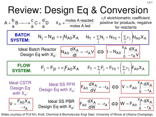
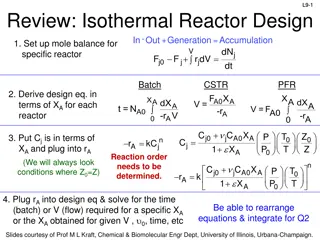
Understanding reactor design involves considerations such as desired conversion, selectivity, and kinetics. Key concepts include rate laws, molar balances, and reactor types. Through molar balance equations and reactor design processes, one can derive essential equations for ideal batch, CSTR, and PFR reactors. The goal is to grasp the methodology rather than memorize specific equations. Professor M.L. Kraft from the University of Illinois at Urbana-Champaign provides valuable insights in these slides.
Download Presentation

Please find below an Image/Link to download the presentation.
The content on the website is provided AS IS for your information and personal use only. It may not be sold, licensed, or shared on other websites without obtaining consent from the author.If you encounter any issues during the download, it is possible that the publisher has removed the file from their server.
You are allowed to download the files provided on this website for personal or commercial use, subject to the condition that they are used lawfully. All files are the property of their respective owners.
The content on the website is provided AS IS for your information and personal use only. It may not be sold, licensed, or shared on other websites without obtaining consent from the author.
E N D
Presentation Transcript
L2-1 Review: What size reactor(s) to use? Answers to this questions are based on the desired conversion, selectivity and kinetics Kinetics Reactor type & size Conversion & selectivity Material & energy balances Slides courtesy of Prof M L Kraft, Chemical & Biomolecular Engr Dept, University of Illinois at Urbana-Champaign.
L2-2 Review: Rate Law for rj rA: the rate of formation of species A per unit volume [e.g., mol/m3 s] -rA: the rate of a consumption of species A per unit volume + A= r kC C A B products A B 1st order in A, 1st order in B, 2nd order overall n A= r kC nth order in A A k + C 1 k A C = r Michaelis-Menton: common in enzymatic reactions A 1 2 A rj depends on concentration and temperature: E a RT = -r Ae A: pre-exponential factor E R :ideal gas constant T:temperature C Arrhenius dependence on temperature :activation energy A A A Slides courtesy of Prof M L Kraft, Chemical & Biomolecular Engr Dept, University of Illinois at Urbana-Champaign.
L2-3 L2-3 Review: Basic Molar Balance (BMB) Fj0 Fj Gj System volume Rate of flow of j out of system Rate of flow of j into system Rate of generation of j by chemical rxn Rate of decomposition of j Rate of accumulation - + - = dN dt ( dt j + = F F G j0 j j mol s mol s mol s d ) mol If the system is uniform throughout its entire volume, then: G ( )( ) j r = V j Moles j generated per unit time (mol/s) Moles generated per unit time and volume (mol/s m3) Volume (m3) = Slides courtesy of Prof M L Kraft, Chemical & Biomolecular Engr Dept, University of Illinois at Urbana-Champaign.
L2-4 L2-4 Review: BMB Equations Fj0 Fj Gj System volume In Out - +Generation =Accumulation dN dt j + = F F G j0 j j dN dt dN dt j r V + = F F uniform rate n V i j0 j j V j + = F F r dV nonuniform rate in V j0 j j Next: Apply BME to ideal batch, CSTR, & PFR reactors Slides courtesy of Prof M L Kraft, Chemical & Biomolecular Engr Dept, University of Illinois at Urbana-Champaign.
L2: Reactor Molar Balances & Considerations L2-5 L2-5 Fj0 Fj Gj reactor Today we will use BMB to derive reactor design equations. Your goal is to learn this process, not to memorize the equations! Slides courtesy of Prof M L Kraft, Chemical & Biomolecular Engr Dept, University of Illinois at Urbana-Champaign.
L2-6 L2-6 Batch Reactors Properties Reactants are placed in the reactor, and the reaction is allowed to proceed for some amount of time Closed system- no addition of reactants or removal of products during the reaction Unsteady-state conditions- the composition changes with time Ideal batch reactor- vessel is perfectly mixed Concentration and temperature are spatially constant, but NOT constant in TIME Slides courtesy of Prof M L Kraft, Chemical & Biomolecular Engr Dept, University of Illinois at Urbana-Champaign.
L2-7 L2-7 Examples of Batch Reactor Lab-Scale Batch Reactor Typical Commercial Batch Reactor Motor for agitation Slides courtesy of Prof M L Kraft, Chemical & Biomolecular Engr Dept, University of Illinois at Urbana-Champaign.
L2-8 L2-8 Basic Mole Balance for Batch Reactor No flow in or out! Fj0 X 0 0 In Out - +Generation = Accumulation V j j 0j FjX dN j + = F F r dV dt V dN Batch Reactor Design Equation j = r dV j dt If the reactor is perfectly mixed, the temperature, concentration, & therefore the reaction rate are spatially constant: dN dt Ideal Batch Reactor Design Equation j = r V j Slides courtesy of Prof M L Kraft, Chemical & Biomolecular Engr Dept, University of Illinois at Urbana-Champaign.
Continuous Stirred Tank Reactor (CSTR) Properties L2-9 L2-9 Continuously add reactants and remove products (open system) Inlet stream instantaneously mixes with bulk of reactor volume Ideal batch reactor- assume perfect mixing occurs in vessel Temperature and concentration are uniform throughout space Composition of the exit stream is the same as that inside reactor (CA,outlet =CA, tank) Steady-state conditions- the reaction rate is the same at every point and does not change with time Slides courtesy of Prof M L Kraft, Chemical & Biomolecular Engr Dept, University of Illinois at Urbana-Champaign.
L2-10 L2-10 Examples of CSTRs Laboratory-Scale Bioreactor Pfaudler Inc. Slides courtesy of Prof M L Kraft, Chemical & Biomolecular Engr Dept, University of Illinois at Urbana-Champaign.
L2-11 L2-11 Basic Mole Balance for CSTR Fj0 Fj In Out - +Generation = Accumulation dN dV r j = + CSTR is at steady state (SS), so no change in moles j with time! V j F F 0j j dt 0 V Steady State CSTR Design Equation + = F F r dV 0 0j j j A perfectly mixed CSTR has no spatial variations in reaction rate + = F F r V 0 Rearrange to put in terms of V 0j j j rj is measured at the outlet because Cj,exit =Cj,tank Ideal Steady State CSTR Design Equation F F 0j j = V r j Slides courtesy of Prof M L Kraft, Chemical & Biomolecular Engr Dept, University of Illinois at Urbana-Champaign.
L2-12 L2-12 Ideal SS CSTR Design Equation F V = F 0j j r j Reactor volume required to reduce the entering flow rate of species j from Fj0 to Fj at the outlet (and in the tank) How do we determine the molar flow rate, Fj (units = mol/time)? ( C )( ) = jF j moles j time moles volume volume time = Cj: concentration of j : volumetric flow rate Ideal SS CSTR design equation in terms of concentration: C C 0 j j V = r j Slides courtesy of Prof M L Kraft, Chemical & Biomolecular Engr Dept, University of Illinois at Urbana-Champaign.
Plugged Flow Reactor (PFR) Properties L2-13 L2-13 Also called a tubular reactor Cylindrical pipe with openings at both ends Steady movement of material down length of reactor Reactants are consumed as they flow down the length of the reactor Operated at steady state: No radial variation in temperature, concentration, or reaction rate All fluid/gas elements have the same residence time Slides courtesy of Prof M L Kraft, Chemical & Biomolecular Engr Dept, University of Illinois at Urbana-Champaign.
L2-14 L2-14 Industrial PFRs Polyethylene reactor: 16 inch inner diameter Operates at 35,000 psi & 600 F Has a vertical orientation when in use Courtesy of Autoclave Engineers of Snap-tite, Inc. Slides courtesy of Prof M L Kraft, Chemical & Biomolecular Engr Dept, University of Illinois at Urbana-Champaign.
L2-15 L2-15 Mole Balance PFR In a plug flow reactor the composition of the fluid varies from point to point along a flow path. Consequently, the material balance for a reaction component must be made for a differential element of volume V V FA0 FA dNj rj V - + = Fj0 Fj dt dN dt 0 Divide by V j + = r V + = F F r V 0 F F j j j j j j + V V V + V V V V lim V 0 dF dV= F F F F j j j + j V V V j V + r V V V = + = r r 0 j j j V Ideal SS PFR Design Eq. If we assume the PFR is ideal, the degree of completion is not affected by PFR shape, only by PFR volume Slides courtesy of Prof M L Kraft, Chemical & Biomolecular Engr Dept, University of Illinois at Urbana-Champaign.
L2-16 L2-16 Packed Bed Reactors (PBR) Cylindrical shell, vertically oriented Often gravity-driven flow Heterogeneous reaction: fixed bed of catalyst inside Reactants enter top and flow through the packed bed of catalyst Concentration gradient of reactant and product down the length of the reactor Reaction occurs on the surface of the catalyst pellets Reaction rate is based on the mass of the solid catalyst, W, not reactor volume V Slides courtesy of Prof M L Kraft, Chemical & Biomolecular Engr Dept, University of Illinois at Urbana-Champaign.
L2-17 L2-17 Mole Balance- Packed Bed Reactor (PBR) dF Similar to PFR, but we want to express it in terms of catalyst weight instead of reactor volume j = r j dV mol mol Units for the rate of a homogeneous rxn (rj) : Units for the rate of a catalytic rxn (rj ) : 3 s catalyst kg s m So rewriting the PFR design equation in terms of catalyst weight instead of reactor volume: dF j= where ' r j W weight the is of catalyst the dW Slides courtesy of Prof M L Kraft, Chemical & Biomolecular Engr Dept, University of Illinois at Urbana-Champaign.
L2-18 L2-18 Mole Balances on Common Reactors Reactor Mole Balance Comment dN dt No spatial variation Batch j = r V j -F -r F No spatial variation, steady state Steady state CSTR j0 j = V j dF dV= j dF dW PFR j r j Steady state PBR j = r Slides courtesy of Prof M L Kraft, Chemical & Biomolecular Engr Dept, University of Illinois at Urbana-Champaign.
L2-19 L2-19 Selection of Reactors Batch small scale production of expensive products (e.g. pharmacy) high labor costs per batch difficult for large-scale production CSTR: most homogeneous liquid-phase flow reactors when intense agitation is required relatively easy to maintain good temperature control the conversion of reactant per volume of reactor is the smallest of the flow reactors - very large reactors are necessary to obtain high conversions PFR: most homogeneous gas-phase flow reactors relatively easy to maintain usually produces the highest conversion per reactor volume (weight of catalyst if it is a packed-bed catalyze gas reaction) of any of the flow reactors difficult to control temperature within the reactor hot spots can occur Slides courtesy of Prof M L Kraft, Chemical & Biomolecular Engr Dept, University of Illinois at Urbana-Champaign.
L2-20 L2-20 Uses for Various Reactors Noncatalytic homogeneous gas reactor Homogeneous liquid reactor Liquid-liquid reactor Gas-liquid reactor Non-catalytic gas-solid reactor Fixed bed Fluidized bed Fixed bed catalytic reactor Fluid bed catalytic reactor Gas-liquid-solid reactor Ethylene polymerization (high pressure) Mass polymerization of styrene Saponification of fats Nitric acid production Iron production Chlorination of metals Ammonia synthesis Catalytic cracking (petroleum) Hydrodesulphurization of oils Slides courtesy of Prof M L Kraft, Chemical & Biomolecular Engr Dept, University of Illinois at Urbana-Champaign.


