Team Project Showcase: Simulated Assembly Line and Processing Workstation

Explore a multidisciplinary team's endeavor in designing a simulated assembly line system for Tallahassee Community College's Advanced Manufacturing and Training Center. Meet the team members, learn about the project objectives, delve into the background, and discover the engineering characteristics and functional aspects involved in this innovative educational tool development.

Download Presentation

Please find below an Image/Link to download the presentation.
The content on the website is provided AS IS for your information and personal use only. It may not be sold, licensed, or shared on other websites without obtaining consent from the author. Download presentation by click this link. If you encounter any issues during the download, it is possible that the publisher has removed the file from their server.
E N D
Presentation Transcript
Simulated Assembly Line and Processing Workstation Team 520 1 Department of Mechanical Engineering
Team Introductions Cheyenne Laurel Project Manager David DiMaggio Design Engineer Boluwatife Olabiran Software Engineer JoEll Williams Hardware Engineer Nataajah Taylor Test Engineer 2 Department of Mechanical Engineering
Sponsor and Advisor TCC Representative Bobette Stubblefield TCC Representative Dylan Sutton Team Advisor Dr. Dorr Campbell Cheyenne Laurel 3 Department of Mechanical Engineering
Objective Tallahassee Community College (TCC) requires an assembly line system to be used in their Advanced Manufacturing and Training Center as an educational tool. Will be used as a Mechatronics certification tool. Must allow for user to toggle failures in the hardware and software to allow for student diagnosis and repair. Figure 1: Advanced Manufacturing and Training Center at TCC 4 Department of Mechanical Engineering
Project Background Cheyenne Laurel 5 Department of Mechanical Engineering
House of Quality Determined the most important engineering characteristics to be: PLC Programming Accuracy of Physical Property Sorting Accuracy of Material Detection Accuracy of Size Detection Table 1: House of Quality 6 Department of Mechanical Engineering
Functional Decomposition Green- Overall Function Goal Blue- 3 Main Functions to be achieved Pink- Secondary Functions Orange- Physical Components Yellow- Measurable Inputs and Outputs Figure 2: Functional Decomposition 7 Department of Mechanical Engineering
Concept Generation Boluwatife Olabiran 8 Department of Mechanical Engineering
Morphological Chart Highlights concept per function. Total of 617 possible concepts. Narrowed down to 8 designs for Concept Selection. Table 2: Concept Generation Chart 9 Department of Mechanical Engineering
Datum Concept Photoelectric sensor Electric Actuator 2 Diverter Arms 2 Capacitive sensors Actuator pushes object to second conveyor belt based on size. Figure 3: Datum Concept 10 Department of Mechanical Engineering
Concept 3 2 Photoelectric Sensor 1 Capacitive Sensor 1 Diverter Arm 2 Conveyor Belts Diverter arm programmed at angles to guide objects in corresponding bins. Concept 3 11 Department of Mechanical Engineering
Concept Selection Boluwatife Olabiran 12 Department of Mechanical Engineering
Pugh Chart Pugh Selection Matrix Alternative Concepts Engineering Criteria Acuracy of Property Sorting Accuracy of Material Detection Acuracy of Size Detection Average Cycle Time Cost Complexity of Programming Fixability Machinability Ease of Modularity Weight 5 5 5 2 3 3 3 4 3 1 + 0 0 0 + + 0 0 + 2 + - 0 + - - - + + 3 + - 0 0 + + + + + 4 0 + + 0 - 0 0 - 0 5 + 0 0 - - - 0 - - 6 - 0 0 0 0 0 - 0 0 7 0 0 0 0 0 0 0 0 - DATUM Sum of Positives Sum of Negatives Sum of Sames Weighted Sum of Positives Weighted Sum of Negatives Score 4 0 5 4 4 1 6 1 2 2 2 5 1 5 3 5 0 2 7 0 2 -2 0 1 8 0 3 -3 14 0 14 14 14 0 21 5 16 10 7 3 15 -10 Table 3: Pugh Chart 13 Department of Mechanical Engineering
Final Ratings Matrix Selection Criteria Accuracy of Property Sorting Accuracy of Material Detection Accuracy of Size Detection Average Cycle Time Cost Complexity of Programming Fixability Machinability Ease of Modularity Concept 1 0.30 0.19 0.28 0.19 0.08 0.10 0.25 0.25 0.33 Concept 3 0.37 0.08 0.64 0.75 0.72 0.69 0.66 0.66 0.33 Concept 4 0.33 0.72 0.07 0.75 0.19 0.21 0.09 0.09 0.33 Table 4: Final Rating Matrix 14 Department of Mechanical Engineering
Embodiment Nataajah Taylor 15 Department of Mechanical Engineering
Manufacturing Technology Dorner 2200 Conveyor Belt: Small Part Handling and Positioning Photoelectric Sensors: Uses a light transmitter and receiver to test if object is in sensing area, as well as detecting size Inductive Sensor: Detects metal using magnetic fields when the object touches the sensor Figure 8: Photoelectric Sensor Figure 7: Dorner 2200 Conveyor Belt Figure 9: Inductive Proximity sensor Nataajah Taylor 16 Department of Mechanical Engineering
PLC Technology Allen-Bradley MicroLogix 1100: 2 analog inputs, 10 digital inputs and 6 digital outputs Solid State Memory Ethernet Connection Port PLC s contain necessary relays, timers, coils and other components that would be required for a relay logic system. Figure 10: Allen- Bradley MicroLogix 1100 PLC PLC s are also ruggedized to withstand temperature ranges, electrical noises, vibrations, and impacts. Nataajah Taylor 17 Department of Mechanical Engineering
Failure Modes and Effects Analysis Allows for the anticipation of failures in a design or manufacturing process. Requires each component to have three different failure ratings (1-10): Severity How hazardous is the failure? How much will it disrupt the process? Occurrence How often is the part likely to fail? Detection How likely is the system able to detect the failure? Risk Priority Number (RPN)= ???????? ?????????? ????????? Nataajah Taylor 18 Department of Mechanical Engineering
FMEA Form Potential Failure Mode Potential Failure Effects OCCURRENCE (1 - 10) Process Step/Input Potential Causes Current Controls Action Recommended DETECTION (1 - 10) SEVERITY (1 - 10) RPN What is the impact on the customer if this failure is not prevented or corrected? What causes the step, change or feature to go wrong? (how could it occur?) What are the recommended actions for reducing the occurrence of the cause or improving detection? What is the process step, change or feature under investigation? In what ways could the step, change or feature go wrong? What controls exist that either prevent or detect the failure? Dirty Lens Wrong Size Reading or No Reading Wrong Size Reading or No Reading Failure to Upkeep Visual Inspection Make sure to clean lenses on a regular basis. Test to make sure that receiever and transmitter are aligned initially. Photoelectric Sensor 10 7 4 280 Reciever Misalignment Initial Misalignment Visual Inspection 10 2 3 60 Vibration Causing Misalignment Wrong Size Reading or No Reading Machine Vibration and Movement Visual Inspection Proper installation of other moving parts that reduces vibration. 10 5 3 150 Capacative Sensor Too Far Away to Wrong Material Reading or No Reading Improper Placement on Conveyor Belt Metal Feather Arm Metal Feather Arm should push all objects within range of sensor. Read Current 10 8 3 240 Fautly Calibration Wrong data Improper Calibration when First Programming Human Data Inspection Check Sensor Inputs during Testing to Confirm Correct Calibration input/output Failure Modes and Effects Analysis 9 2 3 54 Belt Deviation Incorrect Processing of Materials Improper Maintenance and Installation Proper Installation and Maintenance Make sure that conveyor is balanced, and belt is properly placed on conveyor cylinders. Conveyor Belt 8 2 4 64 FMEA Form Belt Motor Failure Conveyor Belt Deterioration over Time Maintenance and Inspection Do not run motor at excessive speeds or weights that may cause overheating. Potential Failure Mode Potential Failure Effects Stops Moving Process Step/Input Potential Causes OCCURRENCE (1 - 10) Current Controls Action Recommended 10 1 3 30 DETECTION (1 - 10) SEVERITY (1 - 10) Incorrect Voltage Application Exessive Heat and Failure Lack of Surge Protection Proper Voltage Application and Protection Use a limiting range of voltages that will not overpower the wiring's insolation. Servo Motor RPN What is the impact on the customer if this failure is not prevented or corrected? What causes the step, change or feature to go wrong? (how could it occur?) What are the recommended actions for reducing the occurrence of the cause or improving detection? What is the process step, change or feature under investigation? In what ways could the step, change or feature go wrong? What controls exist that either prevent or detect the failure? 10 6 4 240 Excessive Vibration Motor Failure Proper Installation and Maintenance of other Moving Parts Maintenance and Inspection Properly mount and attach all moving parts to reduce unnecessary vibrations. Dirty Lens Wrong Size Reading or No Reading Wrong Size Reading or No Reading Failure to Upkeep Visual Inspection Make sure to clean lenses on a regular basis. Test to make sure that receiever and transmitter are aligned initially. Photoelectric Sensor 10 5 5 250 10 7 4 280 Reciever Misalignment Initial Misalignment Visual Inspection Excessive Heat Motor Failure Running the Motor at Too High of Voltage Proper Voltage Application and Protection Avoid incorrect voltage application (above) and excessive vibration (above). 10 2 3 60 10 4 4 160 Vibration Causing Misalignment Wrong Size Reading or No Reading Machine Vibration and Movement Visual Inspection Proper installation of other moving parts that reduces vibration. 10 5 3 150 Arm Breaks Failure to Process Objects Failure due to Normal Stress Repetition Replacement of Piece Offer multiple replacements of the arm in case of failure. Testing and Validation Stage should ensure code is operable. Physically Rotating Arm 6 3 3 54 Capacative Sensor Too Far Away to Wrong Material Reading or No Reading Improper Placement on Conveyor Belt Metal Feather Arm Metal Feather Arm should push all objects within range of sensor. Improper Coding Failure to Run Program Improper Coding No Current Controls are in Place to Provide Proper Code PLC Software Read Current 10 8 3 240 10 3 10 300 Fautly Calibration Wrong data Improper Calibration when First Programming Human Data Inspection Check Sensor Inputs during Testing to Confirm Correct Calibration Connection Issues No Data Input from one of the Components Motherboard Malfunction System Bad Electrical Connections Human Inspection Testing Connections and input reading prior to operation. Purchase New PLC PLC Hardware input/output 9 2 3 54 8 4 5 160 No CPU to Run Faulty Manufacturing No Current Controls are in Place to Decide if CPU is working properly Belt Deviation Incorrect Processing of Materials Improper Maintenance and Installation Proper Installation and Maintenance Make sure that conveyor is balanced, and belt is properly placed on conveyor cylinders. Conveyor Belt 10 2 7 140 8 2 4 64 Belt Motor Failure Conveyor Belt Deterioration over Time Maintenance and Inspection Do not run motor at excessive speeds or weights that may cause overheating. Stops Moving 10 1 3 30 Incorrect Voltage Application Exessive Heat and Failure Lack of Surge Protection Proper Voltage Application and Protection Table 6: Failure Modes and Effects Analysis Use a limiting range of voltages that will not overpower the wiring's insolation. Servo Motor Nataajah Taylor 10 6 4 240 Excessive Vibration Motor Failure Proper Installation and Maintenance of other Moving Parts Maintenance and Inspection Properly mount and attach all moving parts to reduce unnecessary vibrations. 19 10 5 5 250 Department of Mechanical Engineering Excessive Heat Motor Failure Running the Motor at Too High of Voltage Proper Voltage Application and Protection Avoid incorrect voltage application (above) and excessive vibration (above). 10 4 4 160 Arm Breaks Failure to Process Objects Failure due to Normal Stress Repetition Replacement of Piece Offer multiple replacements of the arm in case of failure. Testing and Validation Stage should ensure code is operable. Physically Rotating Arm 6 3 3 54 Improper Coding Failure to Run Program Improper Coding No Current Controls are in Place to Provide Proper Code PLC Software 10 3 10 300 Connection Issues No Data Input from one of the Components Motherboard Malfunction System Bad Electrical Connections Human Inspection Testing Connections and input reading prior to operation. Purchase New PLC PLC Hardware 8 4 5 160 No CPU to Run Faulty Manufacturing No Current Controls are in Place to Decide if CPU is working properly 10 2 7 140
Failure Modes and Effects Analysis FMEA Summary Sensors have high RPNs due to their sensitivity to outside factors. Servo Motor is also susceptible to failure if the voltage supply is incorrect, as well as outside factors like vibrations. PLC Software/Programming has to be correct in order for system to run. Component Photoelectric Sensor Capacative Sensor Servo Motor Risk Priority Number 280 240 240 250 300 Table 7: FMEA Summary PLC Software Nataajah Taylor 20 Department of Mechanical Engineering
Design and Construction David DiMaggio 21 Department of Mechanical Engineering
Project Design Consists of a multiple step process: Step 1: An object is placed on the conveyor belt. Step 2: Inductive and Photoelectric sensors detect if object is present, as well as size and material. Step 3: Diverter arm, attached to a motor, moves the object to correct position for sorting based on received sensor information. Figure 11: Assembly Line CAD David DiMaggio 22 Department of Mechanical Engineering
Sorting Angles 0 - Big and plastic 28 - small and plastic 50 - Big and metal 71 - Small and metal A big object will be greater than or equal to 2 inches. A small object will be less than 2 inches Figure 12: Sorting Angles David DiMaggio 23 Department of Mechanical Engineering
Manufacturing Sensors, servo motor, and diverter arm are assembled. Wiring of different components to the PLC is currently in progress. Testing of each component with the PLC is currently in progress. Figure 13: Current System Set-Up David DiMaggio 24 Department of Mechanical Engineering
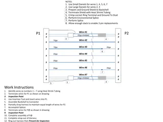
Wiring Diagram 1.DC Power Supply Brown Connection to +24 V terminal Black Connection to 24 V terminal Blue Grounded to 0 V 2.Inputs Orange - Inductive sensor port Yellow - Photoelectric Switch Purple Capacitive Sensor 3.Output(s) Red Servo Motor port Figure 14: Wiring of Inputs/Outputs for PLC JoEll Williams 25 Department of Mechanical Engineering
Programming RUNG 000: The inductive sensor adjusts the stepper motor position RUNG 001: The Master coil is a variable that use the output as an input Each RUNG consists of functions and inputs that use the Logic AND to produce an output. The Servo Motor is the only hardwired output. Figure 15: PLC Programming JoEll Williams 26 Department of Mechanical Engineering
Lessons Learned 1. 3D printed parts will never be perfect the first iteration. 2. PLC Programming is more straight forward than websites make it out to be. 3. Bureaucracy plays a major factor in project development. JoEll Williams 27 Department of Mechanical Engineering
Future Work Team 520's Gantt Chart 1/18/19 1/28/19 2/7/19 2/17/19 2/27/19 3/9/19 3/19/19 3/29/19 4/8/19 4/18/19 Abstract Webpage Dev & Update 3d Print Sensor Mount Mount sensors Assemble conveyor belts High Resolution Graphic DR5 Risk Assessment Order servo motor 3d print diverter arm Conference paper identification Acquire bins for sorting Acquire objects to be sorted Poster Acquire PLC Mount motor to conveyor belt Connect arm to motor Connect sensors to PLC Connect servo motor to PLC Connect conveyor belts to PLC DR6 Conference paper Operational Manual Engineering Design Day Prototype demo Final report End of project JoEll Williams 28 Department of Mechanical Engineering
References 1. CEIA , THS, Metal Detector, 2011, Serial number 20800450034, aperture 550 x 75mm, belt 2750 x 500mm .This items will be. (n.d.). Retrieved from https://www.go-dove.com/en/auction/view?id=13216983 2. 48mm Retroreflective Cylindrical Photoelectric Sensor; Max. Sensing Distance: 3.0m. Grainger - For the Ones Who Get It Done., www.grainger.com/product/TELEMECANIQUE-SENSORS-48mm-Retroreflective-Cylindrical- 32J327?searchBar=true&searchQuery=32J327. 3. Detection Based on Light WhatIs a Photoelectric Sensor? Main Types of Microscopes: Types & Principle KEYENCE Biological Fluorescence Microscopes, www.keyence.com/ss/products/sensor/sensorbasics/photoelectric/info/. 4. 100 Hz Capacitive Cylindrical Proximity Sensor with Max. Detecting Distance 8.0mm. Grainger - For the Ones Who Get It Done., www.grainger.com/product/OMRON-100-Hz-Capacitive-Cylindrical- 2AKD8?searchBar=true&searchQuery=2AKD8. 5. 1200 Hz Inductive Cylindrical Proximity Sensor with Max. Detecting Distance 8.0mm. Grainger - For the Ones Who Get It Done., www.grainger.com/product/EATON-1200-Hz-Inductive-Cylindrical- 40HT96?searchBar=true&searchQuery=40HT96. 29 Department of Mechanical Engineering
Questions? 30 Department of Mechanical Engineering