Harness Assembly Work Instructions for Electrical Wiring
The work instructions outline the preparation, termination, splicing, and assembly steps for harnessing electrical wires in a structured and organized manner. Specific guidelines on using small and large Daniels for different wires, grounding shields, terminating with heat shrink tubing, and crimping ring terminals for grounding are provided. The process involves identifying wires, terminating them as per drawings, performing inspections at key points, inserting wires into connectors, maintaining wire lengths, accomplishing splices, and completing assembly tasks for different wire configurations. The instructions stress the importance of following the specified procedures diligently to ensure a reliable and effective harness assembly.

Download Presentation

Please find below an Image/Link to download the presentation.
The content on the website is provided AS IS for your information and personal use only. It may not be sold, licensed, or shared on other websites without obtaining consent from the author. Download presentation by click this link. If you encounter any issues during the download, it is possible that the publisher has removed the file from their server.
E N D
Presentation Transcript
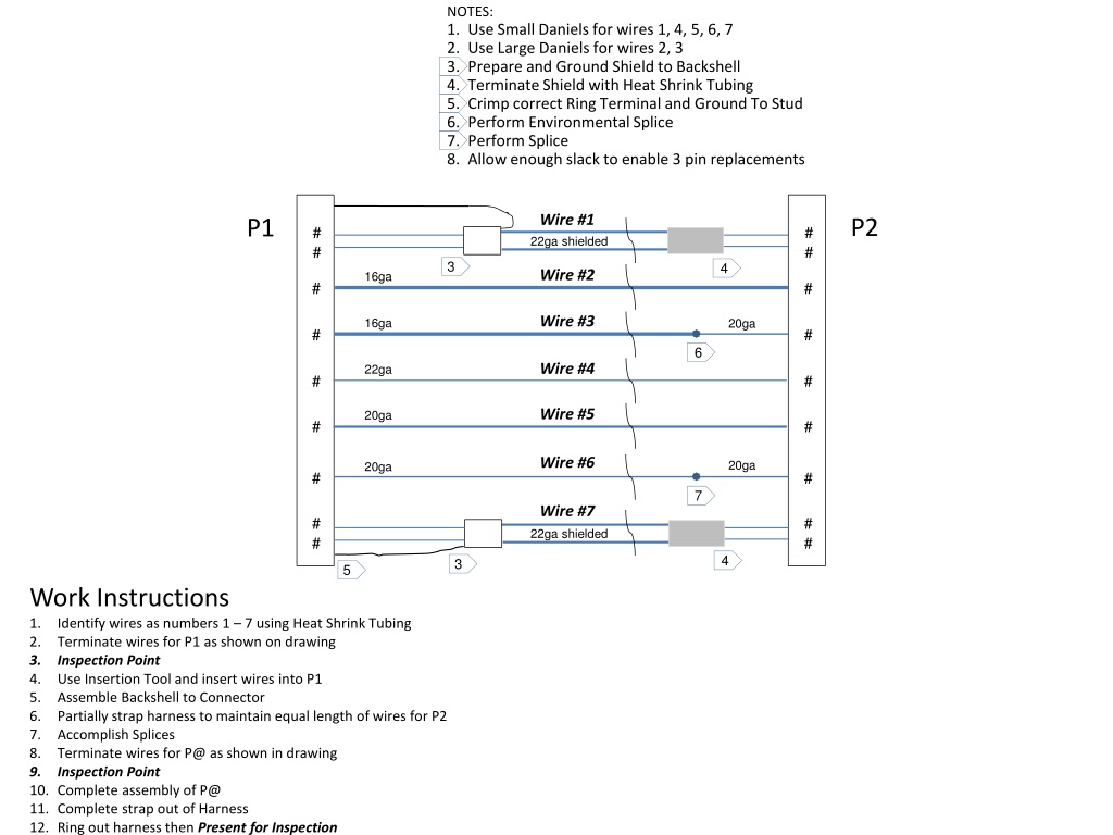
NOTES: 1. Use Small Daniels for wires 1, 4, 5, 6, 7 2. Use Large Daniels for wires 2, 3 3. Prepare and Ground Shield to Backshell 4. Terminate Shield with Heat Shrink Tubing 5. Crimp correct Ring Terminal and Ground To Stud 6. Perform Environmental Splice 7. Perform Splice 8. Allow enough slack to enable 3 pin replacements Wire #1 22ga shielded P2 P1 # # # # 3 4 Wire #2 16ga # # Wire #3 16ga 20ga # # 6 Wire #4 22ga # # Wire #5 20ga # # Wire #6 20ga 20ga # # 7 Wire #7 22ga shielded # # # # 4 3 5 Work Instructions 1. Identify wires as numbers 1 7 using Heat Shrink Tubing 2. Terminate wires for P1 as shown on drawing 3. Inspection Point 4. Use Insertion Tool and insert wires into P1 5. Assemble Backshell to Connector 6. Partially strap harness to maintain equal length of wires for P2 7. Accomplish Splices 8. Terminate wires for P@ as shown in drawing 9. Inspection Point 10. Complete assembly of P@ 11. Complete strap out of Harness 12. Ring out harness then Present for Inspection
NOTES: 1. Use Small Daniels for wires 1, 4, 5, 6, 7 2. Use Large Daniels for wires 2, 3 3. Prepare and Ground Shield to Backshell 4. Terminate Shield with Heat Shrink Tubing 5. Crimp correct Ring Terminal and Ground To Stud 6. Perform Environmental Splice 7. Perform Splice 8. Allow enough slack to enable 3 pin replacements Work Instructions 1. Identify wires as numbers 1 7 using Heat Shrink Tubing 2. Terminate wires for P1 as shown on drawing 3. Inspection Point 4. Use Insertion Tool and insert wires into P1 5. Assemble Backshell to Connector 6. Partially strap harness to maintain equal length of wires for P2 7. Accomplish Splices 8. Terminate wires for P@ as shown in drawing 9. Inspection Point 10. Complete assembly of P@ 11. Complete strap out of Harness 12. Ring out harness then Present for Inspection
NOTES: 1. Use Small Daniels for wires 1, 4, 5, 6, 7 2. Use Large Daniels for wires 2, 3 3. Prepare and Ground Shield to Backshell 4. Terminate Shield with Heat Shrink Tubing 5. Crimp correct Ring Terminal for installation to Ground To Stud 6. Perform Environmental Splice 7. Perform Splice Work Instructions 1. Identify wires as numbers 1 7 using Heat Shrink Tubing 2. Terminate wires for P1 as shown on drawing 3. Inspection Point 4. Use Insertion Tool and insert wires into P1 5. Assemble Backshell to Connector 6. Partially strap harness to maintain equal length of wires for P2 7. Accomplish Splices 8. Terminate wires for P2 as shown in drawing 9. Inspection Point 10. Complete assembly of P2 11. Complete strap out of Harness 12. Ring out harness then Present for Inspection
5 Wire #1 22ga shielded P2 P1 # # # # 4 3 4 Wire #2 16ga # # Wire #3 16ga 20ga # # 5 Wire #4 20ga # # P3 Wire #5 20ga # # Wire #6 20ga 16ga # 6 Wire #7 22ga shielded # # # # 4 4 3 Work Instructions 1. Identify wires as numbers 1 7 using Heat Shrink Tubing 2. Terminate wires for P1 as shown on drawing 3. Inspection Point 4. Use Insertion Tool and insert wires into P1 5. Assemble Backshell to Connector 6. Accomplish Splices 7. Partially temp strap harness to maintain equal length of wires for P2 & P3 8. Accomplish Splices 9. Terminate wires for P2 & P3 as shown in drawing 10. Inspection Point 11. Complete assembly of P2 & P3 12. Remove temp straps, lace main harness at 3 intervals and strap breakout 13. Ring out harness then Present for Inspection NOTES: 1. Use Small Daniels for wires 1, 4, 5,7 2. Use Large Daniels for wires 2, 3, 6 3. Prepare and Ground Shield to Backshell with correctly crimped terminal 4. Terminate Shield with Heat Shrink Tubing 5. Perform Environmental Splice 6. Perform Splice
5 Wire #1 22ga shielded P2 P1 # # # # 4 3 4 Wire #2 16ga # # Wire #3 16ga 20ga # # 5 Wire #4 20ga # # 20ga P3 Wire #5 20ga # # Wire #6 20ga # 6 Wire #7 22ga shielded # # # # 4 3
5 Wire #1 22ga shielded P2 P1 # # # # 4 3 4 Wire #2 16ga # # Wire #3 16ga 20ga # # 5 Wire #4 20ga # # 20ga P3 Wire #5 20ga # # Wire #6 20ga # 6 Wire #7 22ga shielded # # # # 4 3 Work Instructions 1. Identify wires as numbers 1 7 using Heat Shrink Tubing 2. Terminate wires for P1 as shown on drawing 3. Inspection Point 4. Use Insertion Tool and insert wires into P1 5. Assemble Backshell to Connector 6. Accomplish Splices 7. Partially temp strap harness to maintain equal length of wires for P2 & P3 8. Accomplish Splices 9. Terminate wires for P2 & P3 as shown in drawing 10. Inspection Point 11. Complete assembly of P2 & P3 12. Remove temp straps, lace main harness at 3 intervals and strap breakout 13. Ring out harness then Present for Inspection NOTES: 1. Use Small Daniels for wires 1, 4, 5,7 2. Use Large Daniels for wires 2, 3, 6 3. Prepare and Ground Shield to Backshell with correctly crimped terminal 4. Terminate Shield with Heat Shrink Tubing 5. Perform Environmental Splice 6. Perform Splice
Unless otherwise noted, this work is licensed under the Creative Commons Attribution 3.0 Unported License. To view a copy of this license, visit http://creativecommons.org/licenses/by/3.0/. This product was funded by a grant awarded by the U.S. Department of Labor s Employment and Training Administration. The product was created by the grantee and does not necessarily reflect the official position of the U.S. Department of Labor. The Department of Labor makes no guarantees, warranties, or assurances of any kind, express or implied, with respect to such information, including any information on linked sites and including, but not limited to, accuracy of the information or its completeness, timeliness, usefulness, adequacy, continued availability, or ownership. Equal Opportunity Program.