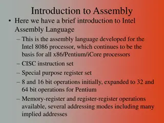
Understanding COSC121: Computer Systems and Assembly Language Programming
Delve into the world of COSC121 led by Assistant Teaching Professor Jeremy Bolton, PhD. Explore essential topics in computer systems, assembly language programming, and hardware design. Get hands-on experience with programming in LC-3, understanding machine language, and writing assembly code. Enhance your skills in debugging, linking, and loading programs. Gain insights into processor architecture, memory systems, and digital design. This course covers a broad spectrum of computer science from operating systems to hardware components.

Download Presentation

Please find below an Image/Link to download the presentation.
The content on the website is provided AS IS for your information and personal use only. It may not be sold, licensed, or shared on other websites without obtaining consent from the author. Download presentation by click this link. If you encounter any issues during the download, it is possible that the publisher has removed the file from their server.
E N D
Presentation Transcript
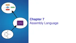
COSC121: Computer Systems Jeremy Bolton, PhD Assistant Teaching Professor Constructed using materials: - Patt and Patel Introduction to Computing Systems (2nd) - Patterson and Hennessy Computer Organization and Design (4th) **A special thanks to Rich Squier
Notes Programming in LC-3 and the Assembler Read PP.6-PP.7 Complete HW #2 and HW#3 Check out the SVN repos Read PennSim docs found in tools/LC3 Assem Simulation
Outline Programming using LC-3 Decomposing procedures into steps contained in ISA Assembly Language Assembly for LC-3 Debugging 2-pass assembly Linking and Loading
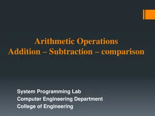
This week our journey takes us Application (Browser) COSC 121: Computer Systems Operating System Compiler Assembler (Win, Linux) COSC 255: Operating Systems Software Drivers Instruction Set Architecture Hardware Processor Memory I/O system Datapath & Control Digital Design Circuit Design transistors COSC 120: Computer Hardware
PP.7 Assembly Language
Human-Readable Machine Language Computers like ones and zeros 0001110010000110 Humans like symbols ; increment index reg. ADD R6,R2,R6 Assembler is a program that turns symbols into machine instructions. ISA-specific: close correspondence between symbols and instruction set mnemonics for opcodes labels for memory locations additional operations for allocating storage and initializing data 7-6
An Assembly Language Program ; ; Program to multiply a number by the constant 6 ; .ORIG x3050 LD R1, SIX LD R2, NUMBER AND R3, R3, #0 ; The inner loop ; AGAIN ADD R3, R3, R2 ADD R1, R1, #-1 ; R1 keeps track of BRp AGAIN ; HALT ; NUMBER .BLKW SIX .FILL x0006 ; .END ; Clear R3. It will ; contain the product. ; the iteration. 1 7-7
LC-3 Assembly Language Syntax Each line of a program is one of the following: an instruction an assember directive (or pseudo-op) a comment Whitespace (between symbols) and case are ignored. Comments (beginning with ; ) are also ignored. An instruction has the following format: LABEL OPCODE OPERANDS ; COMMENTS optional mandatory 7-8
Opcodes and Operands Opcodes reserved symbols that correspond to LC-3 instructions listed in Appendix A ex: ADD, AND, LD, LDR, Operands registers -- specified by Rn, where n is the register number numbers -- indicated by # (decimal) or x (hex) label -- symbolic name of memory location separated by comma number, order, and type correspond to instruction format ex: ADD R1,R1,R3 ADD R1,R1,#3 LD R6,NUMBER BRz LOOP 7-9
Labels and Comments Label placed at the beginning of the line assigns a symbolic name to the address corresponding to line ex: LOOP ADD R1,R1,#-1 BRp LOOP Comment anything after a semicolon is a comment ignored by assembler used by humans to document/understand programs tips for useful comments: avoid restating the obvious, as decrement R1 provide additional insight, as in accumulate product in R6 use comments to separate pieces of program 7-10
Assembler Directives Pseudo-operations do not refer to operations executed by program used by assembler look like instruction, but opcode starts with dot Opcode Operand address Meaning starting address of program end of program allocate n words of storage .ORIG .END .BLKW n n allocate one word, initialize with value n allocate n+1 locations, initialize w/characters and null terminator .FILL n-character string .STRINGZ 7-11
Trap Codes LC-3 assembler provides pseudo-instructions for each trap code so you don t have to remember them. Code Equivalent Description Halt execution and print message to console. Print prompt on console, read (and echo) one character from keybd. Character stored in R0[7:0]. Write one character (in R0[7:0]) to console. HALT TRAP x25 IN TRAP x23 OUT TRAP x21 Read one character from keyboard. Character stored in R0[7:0]. Write null-terminated string to console. Address of string is in R0. GETC TRAP x20 PUTS TRAP x22 7-12
Style Guidelines Use the following style guidelines to improve the readability and understandability of your programs: 1. Provide a program header, with author s name, date, etc., and purpose of program. 2. Start labels, opcode, operands, and comments in same column for each line. (Unless entire line is a comment.) 3. Use comments to explain what each register does. 4. Give explanatory comment for most instructions. 5. Use meaningful symbolic names. Mixed upper and lower case for readability. ASCIItoBinary, InputRoutine, SaveR1 6. Provide comments between program sections. 7. Each line must fit on the page -- no wraparound or truncations. Long statements split in aesthetically pleasing manner. 7-13
Assembly Process Convert assembly language file (.asm) into an executable file (.obj) for the LC-3 simulator. First Pass: scan program file find all labels and calculate the corresponding addresses; this is called the symbol table Second Pass: convert instructions to machine language, using information from symbol table 7-14
First Pass: Constructing the Symbol Table 1. Find the .ORIG statement, which tells us the address of the first instruction. Initialize location counter (LC), which keeps track of the current instruction. 2. For each non-empty line in the program: a) If line contains a label, add label and LC to symbol table. b) Increment LC. NOTE: If statement is .BLKW or .STRINGZ, increment LC by the number of words allocated. 3. Stop when .END statement is reached. NOTE: A line that contains only a comment is considered an empty line. 7-15
Practice ; ; Program to count occurrences of a character in a file. ; Character to be input from the keyboard. ; Result to be displayed on the monitor. ; Program only works if no more than 9 occurrences are found. ; ; ; Initialization ; .ORIG x3000 AND R2, R2, #0 LD R3, PTR GETC LDR R1, R3, #0 ; ; Test character for end of file ; TEST ADD R4, R1, #-4 BRz OUTPUT ; ; Test character for match. If a match, increment count. ; NOT R1, R1 ADD R1, R1, R0 NOT R1, R1 BRnp GETCHAR ADD R2, R2, #1 ; ; Get next character from file. ; GETCHAR ADD R3, R3, #1 LDR R1, R3, #0 BRnzp TEST ; ; Output the count. ; OUTPUT LD R0, ASCII ADD R0, R0, R2 OUT HALT ; ; Storage for pointer and ASCII template ; ASCII .FILL x0030 PTR .FILL x4000 .END Construct the symbol table for the program below (See PP.7) Symbol Address ; R2 is counter, initially 0 ; R3 is pointer to characters ; R0 gets character input ; R1 gets first character ; Test for EOT (ASCII x04) ; If done, prepare the output ; If match, R1 = xFFFF ; If match, R1 = x0000 ; If no match, do not increment ; Point to next character. ; R1 gets next char to test ; Load the ASCII template ; Covert binary count to ASCII ; ASCII code in R0 is displayed. ; Halt machine
Second Pass: Generating Machine Language For each executable assembly language statement, generate the corresponding machine language instruction. If operand is a label, look up the address from the symbol table. Potential problems: Improper number or type of arguments ex: NOT R1,#7 ; what?!?!? ADD R1,R2 ; need more info? ADD R3,R3,NUMBER ; what is NUMBER? Immediate argument too large ex: ADD R1,R2,#1023 Address (associated with label) more than 256 from instruction can t use PC-relative addressing mode 7-17
Notes about labels (from Assembly to Machine) Within the context of assembly, labels generally represent the target address. This may not be intuitive given the ISA structure for an operation. Example: Loads Load Type Syntax Semantics Dreg M[ PC + 9 bOffset ] Load PC relative: LD Dreg 9 bOffset; 0010_001_x_xxxx_xxxx Dreg PC + 9 bOffset Load effective address: LEA Dreg 9 bOffset; 1110_001_x_xxxx_xxxx R1 M[ M[PC + 9 bOffset] ] Load Indirect: LDI Dreg 9 bOffset; 1010_001_x_xxxx_xxxx NOTE: LABEL is NOT the offset. It is the target address. Load Type Syntax Semantics R1 M[LABEL] Load PC relative: LD R1 LABEL; LABEL = PC + offset R1 LABEL Load effective address: LEA R1 LABEL; R1 M[M[LABEL]] Load Indirect: LDI R1 LABEL;
Practice Symbol Test GETCHAR OUTPUT ASCII PTR Address x3004 x300B x300E x3012 x3013 Using the symbol table constructed earlier, translate these statements into LC-3 machine language. ;; Program only works if no more than 9 occurrences are found. ; ; ; Initialization ; .ORIG x3000 AND R2, R2, #0 LD R3, PTR GETC LDR R1, R3, #0 ; ; Test character for end of file ; TEST ADD R4, R1, #-4 BRz OUTPUT ; R2 is counter, initially 0 ; R3 is pointer to characters ; R0 gets character input ; R1 gets first character ; Test for EOT (ASCII x04) ; If done, prepare the output Statement Machine Language LD R3,PTR ADD R4,R1,#-4 LDR R1,R3,#0 BRz OUTPUT 7-19
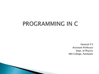
LC-3 Assembler (PennSim) Using assemble (Unix) or LC3Edit (Windows), generates several different output files. PennSim creates two. This one gets loaded into the simulator. 7-20
Object File Format LC-3 object file contains Starting address (location where program must be loaded), followed by Machine instructions Example Beginning of count character object file looks like this: .ORIG x3000 AND R2, R2, #0 LD R3, PTR TRAP x23 0011000000000000 0101010010100000 0010011000010001 1111000000100011 . . . 7-21
Multiple Object Files An object file is not necessarily a complete program. system-provided library routines code blocks written by multiple developers For LC-3 simulator, can load multiple object files into memory, then start executing at a desired address. system routines, such as keyboard input, are loaded automatically loaded into system memory, user code should be loaded in User Space Sometimes designated to be x3000 thru xFDFF each object file includes a starting address be careful not to load object files with overlapping memory addresses 7-22
Linking and Loading Loading is the process of copying an executable image into memory. more sophisticated loaders are able to relocate images to fit into available memory must readjust branch targets, load/store addresses Linking is the process of resolving symbols between independent object files. suppose we define a symbol in one module, and want to use it in another some notation, such as .EXTERNAL, is used to tell assembler that a symbol is defined in another module linker will search symbol tables of other modules to resolve symbols and complete code generation before loading 7-23
Linking and Loading PennSim does not have a linker We will manually perform the linking steps (usually performed by the linker) in Project #1. Labels declared .EXTERNAL are given values at this time
Appendix Jeremy Bolton, PhD Assistant Teaching Professor Constructed using materials: - Patt and Patel Introduction to Computing Systems (2nd) - Patterson and Hennessy Computer Organization and Design (4th) **A special thanks to Rich Squier
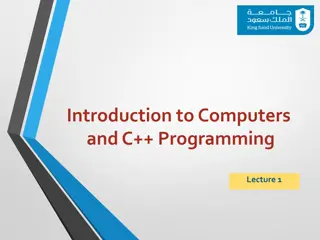
Sample Program Count the occurrences of a character in a file. Remember this? Count = 0 (R2 = 0) Convert count to ASCII character (R0 = x30, R0 = R2 + R0) YES Done? (R1 ?= EOT) Ptr = 1st file character (R3 = M[x3012]) NO Print count (TRAP x21) Match? (R1 ?= R0) YES NO Input char from keybd (TRAP x23) HALT (TRAP x25) Incr Count (R2 = R2 + 1) Load char from file (R1 = M[R3]) Load next char from file (R3 = R3 + 1, R1 = M[R3]) 7-26
Char Count in Assembly Language (1 of 3) ; ; Program to count occurrences of a character in a file. ; Character to be input from the keyboard. ; Result to be displayed on the monitor. ; Program only works if no more than 9 occurrences are found. ; ; ; Initialization ; .ORIG x3000 AND R2, R2, #0 ; R2 is counter, initially 0 LD R3, PTR ; R3 is pointer to characters GETC ; R0 gets character input LDR R1, R3, #0 ; R1 gets first character ; ; Test character for end of file ; TEST ADD R4, R1, #-4 ; Test for EOT (ASCII x04) BRz OUTPUT ; If done, prepare the output 7-27
Char Count in Assembly Language (2 of 3) ; ; Test character for match. If a match, increment count. ; NOT R1, R1 ADD R1, R1, R0 ; If match, R1 = xFFFF NOT R1, R1 ; If match, R1 = x0000 BRnp GETCHAR ; If no match, do not increment ADD R2, R2, #1 ; ; Get next character from file. ; GETCHAR ADD R3, R3, #1 ; Point to next character. LDR R1, R3, #0 ; R1 gets next char to test BRnzp TEST ; ; Output the count. ; OUTPUT LD R0, ASCII ; Load the ASCII template ADD R0, R0, R2 ; Covert binary count to ASCII OUT ; ASCII code in R0 is displayed. HALT ; Halt machine 7-28
Char Count in Assembly Language (3 of 3) ; ; Storage for pointer and ASCII template ; ASCII .FILL x0030 PTR .FILL x4000 .END 7-29


")

")


")
")
")