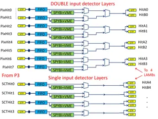
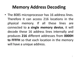
High-Speed Hit Decoder Development for RD53B Chip
Development of a high-speed hit decoder for the RD53B chip by Donavan Erickson from MSEE ACME Lab, focusing on data streams, hitmap encoding, ROM splitting, decode engine building, and more. The process involves encoding methods, ROM setup with borrowed software look-up tables, and buffer systems for streamlined data parsing and decoding.

Download Presentation

Please find below an Image/Link to download the presentation.
The content on the website is provided AS IS for your information and personal use only. It may not be sold, licensed, or shared on other websites without obtaining consent from the author. Download presentation by click this link. If you encounter any issues during the download, it is possible that the publisher has removed the file from their server.
E N D
Presentation Transcript
Development of a High-Speed Hit Decoder for the RD53B Chip Donavan Erickson MSEE ACME Lab
Data Streams > Ccol: Specifies column [4] > Qrow: Specifies quarter row > Hitmap: Encoded hitmap for quarter row > ToTs: Time over Threshold for each hit > IsLast: Drop Ccol if 0 > IsNeighbor: Drops Qrow if 1 Figure 1: Example RD53B stream data with quarter row worth of data highlighted. [4]
Encoding Method Figure 2: RD53B encoding cut pattern.
Hitmap Encoding > Encode using bit pairs (11, 10, 01) [4] > Final encoding {first two bits, first row, second row} > No 00 pairs allows for Huffman encoding > Swap all 01 bits with 0 Figure 3: Hitmap encoding breakdown using two hits Result: 11.101010.010101 Swap 01 with 0 Compressed Result: 11.101010.000
ROM Split > Row data no longer than 14 bits > First 16 bits contain first row > Two ROM split 16-bit ROM for first row 14-bit ROM for second row Figure 4: Encoded hitmap with maximum number of values.
ROM Split > Borrowed software look up table > Creates two ROMs that are 16x32 and 14x16 > Large outputs for meta data and decoded hitmap Figure 5: High level block diagram of split ROM system.
Building Decode Engine Receive and parse data streams Send data to ROMs to be decoded Save and send out decoded data
Decode Engine: Buffering System > FIFO to store stream data > 3 packet buffer for parsing > Index_ptr is moved by data consume state machine > New packets added to buffer as data is consumed Figure 6: Decode engine high level input diagram.
Decode Engine: ROM & data storage > Data consume state machine controls data flow > Creates registered output > Controls sending of encoded hitmap to ROM_wrapper Figure 7: Decode engine high level full diagram.
Decode Engine: Timing > 160 MHz clock > 6 cycles per quarter row > 37.5 ns process time per quarter row > Target data rate of 5.12 Gb/s 4 output lanes at 1.28 Gb/s > Throughput depends on bits per quarter row
Decode Engine: Timing Table 1: Timing estimates for decode engines based off of the number of bits per quarter row. Ccol + Qrow size Hitmap TOT Total Speed Per Engine (Gb/s) # Engine Needed 2 bits (islast and isneighbor active) 4 bits (1 hit, most compressed) 4 bits (1 hit) 10 bits 10bits/37.5ns = 0.267 5.12/0.267 = 19.23 (20) 16 bits 8 bits (Arbitrary number) 4 bits (1 hit) 28 bits 28bits/37.5ns = 0.747 5.12/0.747 = 6.87 (7) 16 bits 20 bits (Arbitrary number) 16 bits (4 hits) 52 bits 52bits/37.5ns = 1.39 5.12/1.39 = 3.70 (4) > Single engine too slow
Decode Engine: Parallelization > Parameterized decode engines > Create a stream distributer to pass data to engines Figure 8: High level diagram of stream distributer with multiple decode engines.
Stream Distributer > Passes data to engines that send a ready signal > One stream per engine > Strips off start of stream bit Figure 9: High level block diagram for stream distributer.
Issue: Parallelization > ROM set per engine too big > One split ROM system is approximately 65.5 BRAMs > Move to a shared centralized ROM Figure 10: High level diagram of stream distributer with multiple decode engines.
Centralized ROM > All engines will share the same ROMs > Possible through offsetting the ROM accesses Figure 11: High level diagram of stream distributer, centralized ROM, and multiple decode engines.
Split ROM Modification > Need to add an access handler > Creates mailbox system for engines > Dual port ROMs for double access Figure 12: High level diagram of the ROM decode shared module.
ROM Timing > 6 cycles to process hitmap > Offset engines > 12 engines with dual port ROMs Figure 13: Timing diagram for the engine offsets for accessing centralized ROM system.
Base Design > General data generation for testing > Test block checks engine accuracy > Good for checking all engines Figure 14: Top level diagram of initial full design for hardware decoder.
Updated Test Design > Dynamically generates data > Only works for one engine right now > Good for checking all hitmap encodings Figure 15: Top level architecture for hardware testing of the hardware decoder. Source Geoff Jones.
Optimizations Logic gate decode > Decode first two bits with logic gates > Changed to two 14x16 ROMs > From 65.5 BRAMs to 15 BRAMs per ROM split system Figure 16: Breakdown of new ROM system 14x16 ROM 2 14x16 ROM 1
Optimizations > 4244 bits per event > Input FIFO 2 -> 1 BRAM > Output FIFO 4 -> 2 BRAMs > Verilog optimizations for LUT savings Figure 17: Conservative estimated event sizes for RD53B.
Optimized Resource Utilization > Using KC 705 board (xc7k325tffg900-2) > Resource usage is estimation for 12 engines > Over 2X savings for LUT and BRAM Figure 18: Initial resource usage versus optimized resource usage.
Interpretation of Results Table 2: Number of engines need based on hits per quarter row and compression. Max/Min compression Ccol + Qrow size Hitmap TOT Total Speed Per Engine (Gb/s) # Engine Needed 1 hit max 2 bits 4 bits 4 bits 10 bits 10/37.5ns = 0.267 5.12/0.267 = 19.23 (20) 1 hit min 16 bits 8 bits 4 bits 28 bits 28/37.5ns = 0.747 5.12/0.747 = 6.86 (7) 2 hit max 2 bits 5 bits 8 bits 15 bits 15/37.5ns = 0.4 5.12/0.4 = 12.8 (13) 2 hit min 16 bits 14 bits 8 bits 38 bits 38/37.5ns = 1.01 5.12/1.01 = 5.069 (6) > Analyzed ATLAS simulation data Average of 1-2 hits per quarter row > Target of 5.12 Gb/s for all layers > 37.5ns per quarter row of data
Resources for Each Configuration Table 3: The summary of resource usage cases for different hardware decoder configurations based on hits per quarter row. Hits per quarter row w/ compression Bits per quarter row Single engine (Gb/s) 12 engine (Gb/s) Engines needed Estimated BRAM usage Estimated LUT usage 1 max 10 bits 0.267 3.2 20 94 42,000 2 max 15 bits 0.4 4.8 13 73 27,300 1 min 28 bits 0.747 8.96 7 38 14,700 2 min 38 bits 1.01 12.16 6 35 12,600 > Each hardware decoder instantiation 15 BRAM for ROM split 2 BRAM for stream distributer Max 12 engines per instantiation > Each decode engine 3 BRAM, 2100 LUTs
Future Work Add additional modes of operation Add Multi-pumping and c-slowing redundancy features
References > [1]. CERN website , CERN, [Online], Available: https://home.cern/ > [2]. High Luminosity LHC Project , CERN, [Online], Available: https://hilumilhc.web.cern.ch/ > [3]. Chistiansen, Jorgen, Loddo, Flavio, RD53 Collaboration Proposal: Extension of RD53 , RD53, September 6, 2018 > [4]. The RD53B Pixel Readout Chip Manual v1.31 , RD53, September, 2020 > [5]. The RD53B Pixel Readout Chip Manual v0.38 , RD53, April 14, 2020 > [6]. 7 Series FPGAs Memory Resources v1.14 , Xilinx, July 3, 2019 > [7]. Timon Heim, private communication, 2021 > [8]. McMahon, Stephen; Pontecorvo, Ludovico, Technical Design Report for the ATLAS Inner Tracker Strip Detector , CERN, April 1, 2017 > [9]. CERN atlas website , CERN, [Online], https://atlas.cern/discover/detector
16x32 ROM > Send first possible 16 bits > Assume hitmap is 20 bits total > First two bits plus first row is 13 bits long > Hitmap > 16 bits use rollback sec row Rollback = 3 16 3 = 13
14x16 ROM > Know position of sec row data > Send next 14 bits > Total hitmap was 20 First row 13 Sec row 7 > Use rollback to find final encoded length Rollback = 7 14 - 7 = 7 > OR decoded hitmaps together
Decode Engine: Data Consume State Machine > Buffer fill stages > Handles empty events > First hitmap sent out while tag read
Decode Engine: Data Consume State Machine > Main processing stages > Stalling feature for slow data > 6 total cycles per quarter row
Interpretation of Results Table 2: Average amount of hits per active quarter row by layer. Layer 3 ATLAS hit data was not provided because layer 3 data is similar enough to data in layer 4 that the same estimates can be used for both. Layer # Average Hits Per Active Quarter Row Layer 0 2.34 Layer 1 1.78 Layer 2 1.98 Layer 4 1.97 > Averages taken from ATLAS simulation data > Layer data for ITk pixel detector > Examine 1 and 2 hit cases