Multi-Product Chip Multiprocessor Floorplan Optimization Framework
This research discusses a framework for optimizing floorplans of chip multiprocessors, considering multiple products with varying requirements. The study emphasizes the interdependency between interconnection networks and floorplans, impacting power, performance, and area. By making floorplans choppable, optimization becomes more efficient across different SKUs of Intel Xeon Server processors. The framework addresses the complexity of chip design and performance enhancement.

Download Presentation

Please find below an Image/Link to download the presentation.
The content on the website is provided AS IS for your information and personal use only. It may not be sold, licensed, or shared on other websites without obtaining consent from the author. Download presentation by click this link. If you encounter any issues during the download, it is possible that the publisher has removed the file from their server.
E N D
Presentation Transcript
Multi-Product Floorplan Optimization Framework for Chip Multiprocessors Marco Escalante1, Andrew B. Kahng2, Michael Kishinevsky1, Umit Ogras3and Kambiz Samadi4 1Intel Corp., 2ECE and CSE, University of California at San Diego 3School of ECEE, Arizona State University, 4Qualcomm Research SLIP 2015 1 1
Outline Big Picture and Motivation Background on Tile-level Floorplanning Multi-product Chip Floorplanner Generic Formulation Choppability constraints for multi-product optimization Experimental results Conclusions and future work 2 2
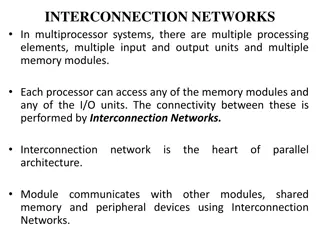
Big picture Interconnection networks commonly used in industry Servers Ring and mesh Graphics / Throughput computing mesh Clients Rings Cyclic dependency between interconnection network and floorplan Interconnection network depends on tile and chip floorplan Floorplan depends on interconnection network core core core Cache should be wide enough to support link width core core core Cache Cache Cache Cache Cache Cache core core Cache Cache Both floorplan and interconnect topology affect Power/Performance/Area 3 3
Current Examples: Chip-Multiprocessors Last level cache (LLC) Memory controllers (MC) & channels I/O controller(s) QPI controller(s) Power control unit (PCU), PCU Memory Controller Core* C C Q P I R R R LLC LLC LLC C C C R R R LLC LLC LLC P C I e C C C LLC LLC LLC R R R C C C Same resources (building blocks) used for many SKUs MC MC * Picture of a low core count system is drawn for illustrative purposes. Core box entails mid-level caches and other common blocks in all cores 4 4
Multi-product FP optimization Different SKUs with varying requirements Different number of cores, memory channels, I/O agents yet share the same building blocks Make the FP choppable to the optimization once and re-use for all Intel Xeon Server processor Haswell had 27 different SKUs, with number of cores ranging from 4 to 18 QPI 1 QPI R3CS QPI 0 QPI 2 QPI PCIe IIO PC U R3CS I I core core core core core core Cache Cache Cache Cache Cache Cache core core core Cache Cache Cache core core core Cache Cache Cache core core core Cache Cache Cache MC MC VMSE 1/2 VMS E3 VMSE 0 MC MC IV Town 15 cores 5 5
Overview of Approach Goal: Develop an efficient and robust floorplan optimization framework for server products Involves floorplanning at two levels of hierarchy: (1) tile-level, ~10-20 resources (2) chip-level, many tiles (> 20 tiles) Tile-level FP considers the physical constraints due to interconnect Chip-level FP addresses choppability constraints by simultaneously optimizing the FP across product classes 6 6
Tile Floorplanning Objective: Minimize area Subject to: Global routing constraints NoC link width Major resources Core, LLC and MLC caches, Core-MLC interface, LLC/MLC - Ring interface, snoop filter, etc. Resources can be both hard or soft Hard blocks can rotate 90 Approach: Mixed-integer linear programming (MILP) Since tile level FP is not the focus of the paper, only major distinct properties will be mentioned Reference: S. Sutanthavibul, E. Shragowitz and J. B. Rosen, An Analytical Approach to Floorplan Design and Optimization , IEEE Trans. on CAD, 10(6), 1991, pp. 761-769. 7 7
Constraints Imposed by Chip FP Routing constraint: Block i and j should not overlap in X and Y directions j j XXX i CORE j j XXX XXX XXX Router Adjacency constraint: Block i and j should be adjacent i j i j i i 8 8
Outline Motivation and Big Picture Background on Tile-level Floorplanner Multi-product Chip Floorplanner Generic Formulation Choppability constraints for multi-product optimization Experimental results Conclusions and future work 9 9
Chip Level Floorplan Overview Floorplans of each class can be easily derived through chopping operation Differences with respect to tile floorplan Overlap constraints are met by default Integer linear programming formulation Simultaneous floorplan optimization across multiple product classes P1 P2 P3 MC Core MC MC Core MC Core Row 1 Chopped Row 0 Core Core Core Core Core y Column 0 1 2 0 1 2 0 1 2 Chopped Chopped x 10 10
Preliminaries and Notations (1,0) (1,1) We use 1-hot binary variables uijsuch that uij = 1 means the cell (i,j) is occupied uij = 0 means the cell (i,j) is empty We need to extend the definition to multiple floorplans usij represents the cell (i,j) in FP s Multiple types of cells, Core, Memory Controller (MC), Empty usij0 means an empty cell at (i,j) in FP s usij1 means a CORE at cell (i,j) in FP s usij2 means an MC at cell (i,j) in FP s Our formulation can consider k resource types (0,0) (0,1) FP: S0 (1,0) (1,1) (0,0) (0,1) FP: S1 (1,0) (1,1) Example at the right hand side (0,0) (0,1) u0001 (Core), u0011 (Core) u0101 (Core), u0112 (MC) FP: S2 Core MC Empty 11 11
Generic Problem Formulation (1,0) (1,1) GOAL: to find {usijk} s to Minimize sum of half-perimeter of all products (0,0) (0,1) FP: S0 (1,0) (1,1) Constraints on number of resources (0,0) (0,1) FP: S1 (1,0) (1,1) Each tile can be occupied by only one type of resource Each product has a specified number of instances of each resource (0,0) (0,1) Monotonicity constraints: Suppose, product i can be chopped to j FP: S2 MC Core Empty 12 12
Choppability (1,0) (1,1) Solution = Finding {usijk} s (0,0) (0,1) Example at right hand sice FP: S0 {u0000 , u0001 } = {0,1} (Core), {u0010 , u0011 } = {0,1} (Core) {u0100 , u0101 } = {0,1} (Core), {u0110 , u0111 } = {1,0} (MC) (1,0) (1,1) {u1000 , u1001 } = {0,0} (Empty), {u1010 , u1011 } = {0,1} (Core) {u1100 , u1101 } = {0,0} (Empty), {u1110 , u1111 } = {1,0} (MC) (0,0) (0,1) FP: S1 {u2000 , u2001 } = {0,0} (Empty), {u2010 , u2011 } = {0,1} (Core) {u2100 , u2101 } = {0,0} (Empty), {u2110 , u2111 } = {0,0} (Empty) (1,0) (1,1) Chop the box = Cores are converted to empty (0,0) (0,1) Chopping a cell means Core or MC converted to Empty FP: S2 Core MC Empty 13 13
Core/MC Count Constraints (1,0) (1,1) Assume NsCore = Number of cores in FP s NsMC = Number of MCs in FP s (0,0) (0,1) FP: S0 Example: N0Core = 3, N1Core = 1, N2Core = 1, N0HA = 1, i j i j (1,0) (1,1) s ij = s Core = u N , for s 2 , 1 , 0 1 (0,0) (0,1) FP: S1 = = s ij s MC , 2 , 1 , 0 u N for s 2 (1,0) (1,1) (0,0) (0,1) usij2 = 1 only if there is an MC in the cell usij1 = 1 only if there is an Core in the cell FP: S2 Core MC Empty 14 14
Height and Width Computations (1,0) (1,1) To express area, we need a way of representing height and width, but we will have s heights and widths For each product class i otherwise , 0 (0,0) (0,1) FP: S0 , 1 = i rck 1 if u K Shows that row r is used = i r , i r used (1,0) (1,1) 0 1 1 c C k (0,0) (0,1) r k , 1 = i rck 1 if u K FP: S1 Shows that column c is used = i c , i c used 0 1 1 R , 0 otherwise (1,0) (1,1) (0,0) (0,1) r r = = i r i c i H h used i W w used i i FP: S2 0 1 0 1 R R Core MC Empty 15 15
Additional Placement Constraints Sources at the boundaries Memory controller channels and I/O controllers Contiguous tiles Adjacency constraints I/O MCh MCh MCh MCh I/O I/O I/O I/O I/O MC MC MC MC MCh I/O MCh MCh MCh I/O MCh MCh I/O MCh MCh MCh MCh MCh MCh MCh I/O MCh MCh MCh MCh MCh 16 16
Power- / Performance-Driven DSE We allow the number of core and memory controllers for each product to vary in a given range given target design thermal power We add constraints on maximum number of memory controllers in a given row or column 17 17
Outline Motivation and Big Picture Background on Tile-level floorplanning Multi-product Chip Floorplanner Generic Formulation Choppability constraints for multi-product optimization Experimental results Conclusions and future work 18 18
Developed Infrastructure Read a floorplan description file # <#rows> <#columns> Biggest product grid size: 6 6 Generate corresponding integer linear programming formulation that is fed into CPLEX N_C_0: 26 N_H_0: 4 N_C_1: 18 N_H_1: 2 Solutions are written into an ascii file describing final floorplans of all the product classes # max-k constraint on HAs MC top: 1 MC bottom: 2 MC left: 1 MC right: 1 The final floorplan description of each product class is printed as a PDF file # Tile width and height information Tile width: 2 Tile height: 1 Multi-Product FP Description File 19 19
Chopping with Four Product Classes S0 = 34 cores, 8 MCs S2 = 18 cores, 2 MCs S1 = 26 cores, 4 MCs S3 = 10 cores, 2 MCs MC MC Core Core Core MC Empty MC Core Core Core Core Core Empty MC Core Core Core Core Core Empty Core Core Core Core Core Core Empty Core Core Core Core Core Core Empty Core Core Core Core Core Core Empty MC Core Core MC Core MC Empty 20 20
Chopping with Four Product Classes S2 = 18 cores, 2 MCs S1 = 26 cores, 4 MCs Core Core Core Core Core Core MC MC Core Core Core Core Core Core Core MC Core Core Core Core Core Core Core MC Core Core Core Core Core Core Core Core Core Core Core Core Core Core Core Core Core Core Core Core Core Core Core Core 21 21
Chopping with Four Product Classes S2 = 18 cores, 2 MCs S3 = 10 cores, 2 MCs MC Core Core Core Core Core Core Core Core MC Core Core Core Core Core Core Core Core Core Core Core Core Core Core Core Core Core Core Core Core Core Core Core Core Core Core Core Core Core Core Core Core Core Core Core 22 22
Results with Memory Controller Channels S1 = 36 cores, 8 MCs, 8 MChs S2 = 27 cores, 6 MCs, 6 MChs MCH8 MCH7 MCH6 E MCH5 MC E MC E MC E MC E C C C C C C C C C C C C C C MCH2 I/O MC C C C C C C C C C C C C C C C C C C C E E MC C C MC C MC MCH3 MCH1 MCH4 E 23 23
Results with Memory Controller Channels S2 = 27 cores, 6 MCs, 6 MChs S3 = 18 cores, 4 MCs, 4 MChs MCH2 MCH3 MCH5 MCH4 MC E MC MC MC C C C C C C C C C C E I/O E C C C C C C C C C C C C C C MC C C C MC MCH1 E MCH6 24 24
Conclusions & Future works Simultaneous floorplan optimization framework for CMPs across multiple products We define the concept of a choppable floorplan Enables us to easily derive the floorplan of smaller products from those of larger Finding choppable floorplans across multiple products to reduce re-design costs and shortens time-to-market Future challenges Joint tile and chip level floorplanning Reducing the white space when 25 25
26 26
Results with Memory Controller Channels S1 = 36 cores, 8 MCs, 8 MChs S2 = 27 cores, 6 MCs, 6 MChs S3 = 18 cores, 4 MCs, 4 MChs Test Case # Binary Variables 595 896 1089 # Constraints CPU Runtime (s) 687 4744 14936 1 2 3 3014 6204 7218 27 27
Different Grid Size MC MC MC MC MC MC MC Grid size is 6 x 6 Total number of tiles = 30 Tile height = 1, Tile width = 2 Enables exploration of different tile aspect ratios MC 28 28
Power- / Performance-Driven DSE (2) We consider different width and height values for different resource types 29 29
Tile Floorplan Examples Logic XXX MISC Pipeline Stages CORE XXX Out. Buffer XXX IDI Inter- face XXX Router XXX XXX XXX Sample Core Floorplan Sample FP for Router &Cache Controller 30 30
Developed Infrastructure Read a floorplan description file # <block name> <area> <minAR> <maxAR> <rotation> BEGIN FP DESCRIPTION X1 A1 minAR1 maxAR1 0 X2 A2 minAR2 maxAR2 1 X3 A3 minAR3 maxAR3 1 X4 A4 minAR4 maxAR4 0 END FP DESCRIPTION Generate corresponding mixed- integer programming formulation that is fed into CPLEX Solutions are written into an ascii file describing final floorplan # <Block 1> <Block 2> <nonoverlapping constraint> BEGIN OVERLAP CONSTRAINTS X2 X4 3 END OVERLAP CONSTRAINTS The final floorplan description is printed as a PDF file at the end #<Block 1> <Block 2> BEGIN ADJACENCY INFO X3 X4 END ADJACENCY INFO Floorplan Description File 31 31


")