Unified Approach for Performance Evaluation and Debug of System on Chip in Early Design Phase
This presentation discusses the challenges related to system-on-chip design, focusing on bandwidth issues, interconnect design, and DDR efficiency tuning. It explores the evolution of performance evaluation methods and the limitations of existing solutions. The need for a unified approach for early-phase evaluation and debugging is emphasized to address the complexities of modern SOC design.

Download Presentation

Please find below an Image/Link to download the presentation.
The content on the website is provided AS IS for your information and personal use only. It may not be sold, licensed, or shared on other websites without obtaining consent from the author. Download presentation by click this link. If you encounter any issues during the download, it is possible that the publisher has removed the file from their server.
E N D
Presentation Transcript
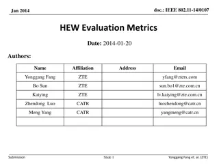
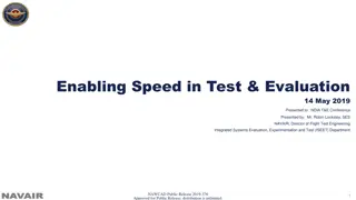
Unified Approach for Performance Evaluation and Debug of System on Chip at Early Design Phase Nishit Gupta Scientist, Ministry of Electronics & Information Technology(MeitY), Government of India
Agenda Introduction Problem statement Alternate solutions and limitations Proposed solutions Performance and Debug Approaches Conclusions
Introduction Problem Statement (Then & Now) BW is a major Issue now 4 GB/s required for a typical IP 4 IP1 Digital TV SOC BW was not an issue IP 5 IP 6 M E M O R Y IP 7 IP2 Available b/w < 4GB/s due to parallel multiple accesses There is a limit on the available BW IP 8 IP 9 IP 10 IC s now IC s during 90-2000 s IP3
Introduction Problem Statement (Typical SoC)
Introduction Problem Statement (Typical Interconnect)
Introduction Problem Statement (Areas of Concern) IP 2 Design a good interconnect and tune it to give a FAIR BW share to every IP IP 1 IP 3 IP 4 M E M O R Y IP 5 IP 7 MIXER IP 6 The IP Traffic Classes: 1. Real time (video IP s) 2. Latency sensitive (processors) 3. High Bandwidth (Video Decoder) IP 9 Tune the DDR accesses for maximizing the efficiency IP 8 IP 10
Introduction Problem Statement (Alternate Solutions & Limitations) 1. Spreadsheet analysis Low accuracy when traffic from different IP s get mixed Tuning the Mixer for best DDR efficiency is not feasible 2. High level C/C++ model for the whole system (including IP, interconnect, DDR subsystem) High level C/C++ models for complex SOC not available. Need a lot of effort to create/maintain for each SOC Low accuracy and not effective correlation with post-silicon results 3. Performance Simulation with SOC RTL Stable SOC RTL available very late. Very Slow though accurate Software drivers for all IP s need to be available 4. Emulation platforms Faster than RTL simulations but results are very late in SOC cycle and availability of s/w drivers on time is difficult RTL changes are very difficult without major impact on schedule
Requirements Model of System of Chip (SOC) at an Abstraction Level which: Available at an Early Design Phase Simulate fast enough Accurate Able to exercise various scenarios
Proposed Solution Embedded s/w dev. Golden Reference Models for Functional verification Rough Power estimation Performance analysis Embedded s/w Power analysis Timing analysis Architecture analysis Performance analysis Rough Power estimation TLM Proposed Solution SoC available in weeks Moderate- accuracy & simulation speed RTL VSOC available in Months Low accuracy & high simulation speed SOC available in years High accuracy & low simulation speed Solution is to use reconfigurable components at abstraction level - Transaction Level Model (TLM) + Bus Cycle Accurate (BCA)
Proposed Solution (Overview) Hard tuning (triggers RTL changes) create applications with a set of Bus Mater s for each Use case Use case is one of the Mixer + DRAM controller Interconnect data path widths Create Bus Mater (IP Traffic Generator) models Model the periodic peak traffic accurately For real time IP s model time IP s Run simulations Check bandwidth and latency values Check FIFO levels for Real several modes in which the parameters Interconnect frequencies Soft tuning Create a platform with BCA+TLM model of the interconnect and actual RTL for the DDR memory subsystem the internal FIFO s accurately chip can operate IP parameters DRAM interface frequency IP FIFO sizes SOC interconnect design ready Interconnect parameters Interconnect topology Change interconnect topology/ frequency /data path widths / IP/size or freq converter FIFO sizes / dram frequency Create Platform + applications for different use cases Simulation run Run Run SysPerf Simulation data (VCD) created Analyze waveforms Sysprobe on VCD generated on VCD Bus Master check FIFO states for real time IP s B/W and latency Values for all the IP s are available Mixer + Memory Ctrl RTL Bus Master Memory Model NO YES . . FIFO BW of all IP s Sufficient? Under/overflows observed? SystemC Wrapper Bus Master NO NO YES YES Interconnect (systemC model) Tune the programmable parameters for Interconnect components + IP ST bus plug + DRAM controller parameters Tried enough Tuning/ simulations? Tune the Programmable SOC Interconnect design is good
What needs to be tuned for good traffic management ? IP parameters Arbitration scheme, Bandwidth limiters Mixer programming for good flow regulation and best DRAM efficiency Freq/size converter IP Node with arbiter Mixer With arbiter Fifo size, Store & forward D R A M DRAM controller Fifo size, Store & forward Fifo size, Store & forward 11
Not able to meet bandwidth, latency requirements ? Look for bottlenecks in the interconnect Run performance simulations and find out.. Run Performance performance simulation results have this info simulations to find out Freq/size converter IP Node with arbiters Mixer With arbiter IP FIFO size increase unavoidable?? DRAM DRAM controller Interconnect topology change may help Frequency increase unavoidable?? Did it work? How much increase is optimal? How much increase is optimal?
Performance Evaluation Approach CFG Result Files SysPerf HW .vcd Simulation time Analysis time Flow Transaction extractions from simulation and Simulation Database Recording Different abstraction levels displayed & visualization of transactions along with signals Features Debug: Transaction recording and Protocol Checking Performance: Analyzers Module (Latencies, BD )
Performance Evaluation Approach (Transaction Recording Module)
Performance Evaluation Approach (Performance Recording Module) Latency (#cycles) - wvalid2wready - bvalid2bready Response packet to Initiator1 Bandwidth 865 MB/s Request packet from Initiator1
Performance Evaluation Approach (Performance Recording Module) Performance Figures Min cycles Max cycles Avg cycles Latency (WVALID to WREADY) 0 197 56 Latency (BVALID to BREADY) 21 30 22 AXI Burst Pipeline 2 3 4 AXI Beat Pipeline 0 8 2 BANDWIDTH 865 MB/s Opcode Table READ 1 Byte (1 bytes * 3) = 3 bytes(0.68%) WRITE 1 Byte (1 bytes * 2) = 2 bytes(0.45%) READ 2 Bytes (2 bytes * 11) = 22 bytes(5%) Number Of Bytes transferred 443 POWER Dissipated IDLE 0.145280W (99.32%) NOP 0.3W (99.67%) COMPUTE 0.7W (99.86%) READ 0.4W (99.75%) WRITE 0.009999999983W (90.91%)
Modeling Approach- Extraction of Memory References Memory References are extracted by running TxE scripts over Value Change Dump (.vcd) files resulted from SoC simulation Further tuned for timing parameters & synchronization and fed to BUS Masters embedded with Cache Simulation Models. $MASTER_NAME $MASTER_PROCESS_SEQ FDMA {1,2,3}*10 # Process 1: IP doing no operation $PROCESS_NAME $PROCESS_SEQ Nop_Operation NOP 500 END # Process 2: FDMA produces traffic noise of 50MB/s on memory area $PROCESS_NAME $PROCESS_BANDWIDTH $PROCESS_DATA_LENGTH $PROCESS_OPCODE $PROCESS_ADDRESS Mem_Write_Access 50 1024 {WRITE32;WRITE16;WRITE8} {(0x0~0x2ff)=20;(0x3ff~0x4ff)=80} # Process 3: IP does read accesses on control register area $PROCESS_NAME $PROCESS_SEQ Read_To_CtrReg START REPEAT 1000 READ16 $addr++ 0xffff
Cache Memory Policies/ Configurations Replacement Policy Least Recently Used First-In-First-Out Random Fetch Policy Demand Fetch Pre-fetch Write hit policy Write Through Write Through Write Back Write Back Write miss policy Write Allocate No Write Allocate Write Allocate No Write Allocate Parameter Explanation Default Value -lN-Tsize Size 32K -lN-Tbsize Block size 1K -lN-Tassoc Associativity (1, 2, 4, ..) (default 1) -lN-Trepl Replacement policy (l=LRU, f=FIFO, r=random) (default 1) -lN-Tfetch Fetch policy (d=demand, prefetch) (default d) -lN-Twalloc Write allocate policy (a=always, n=never) (default a) -lN-Twback Write back policy (a=always, n=never) (default a) -maxcount Stop simulation after U Memory References (default infinite)
Analysis of Simulation Results- Miss Ratio Associativity = 2 Associativity = 4 Associativity = 1 Cache Block Size (Byte) Memory Size 16 32 16 32 16 32 2K 4K 8K 16K 32K 0.0599 0.0429 0.0229 0.0119 0.0071 0.0394 0.0289 0.0155 0.0079 0.0047 0.0517 0.0294 0.0144 0.0069 0.0031 0.0346 0.0203 0.0100 0.0049 0.0021 0.0320 0.0263 0.0121 0.0044 0.0021 0.0150 0.0177 0.0087 0.0032 0.0014
Functional Verification Approach Testbench TLM IPs TB Memory Master C/C++ Abstract interconnect Adapter Adapter IP Verification TLM DUT In-system Verif. RTL DUT 23
Nonintrusive Timing Randomization Probes (NTRP) Based on SystemC Verification Library Configured through input cfg file Introduces Timing Randomization at Communication Interface Random, Constrained, Fixed, Timed/ Cycle delay Selectively adds delay in the transaction ID, Address, Opcode etc. Re-orders transactions/ Introduces Out-of-Order
NTRP- configuration file <timing:set> <timing:id_number>default</timing:id_number> <timing:signal_scope>AWREADY</timing:signal_scope> <timing:conditions> </timing:conditions> <timing:cycle_delay_model>RANDOM</timing:cycle_delay_model> <timing:cycle_delay timing:min="0" timing:max="0" timing:percentage="50"/> <timing:cycle_delay timing:min="20" timing:max="40" timing:percentage="50"/> </timing:set>
NTRP- AXI3 Timing Randomizer (few scenarios) BVALID Delay: Disordering disabled, different BID value BVALID Delay: Disordering enabled, different BID value
Conclusion (Comparison of available solutions) Proposed solution Alternate solution(s) Performance Parameter Spreadsheet High level C/C++ RTL Emulation platform Configurable TLM+BCA Models Schedule impact Very Low Low Very High Low High Low medium medium Overall Effort High High Low Low Low Low Very High medium Low medium Cost of tools medium Simulation time High Very high High medium medium High No of use cases High High High Results Accuracy Very Low Very low
Nishit Gupta Scientist, R&D in Electronics Group, Ministry of Electronics & Information Technology(MeitY), Government of India


")


")