Understanding Capacitor Behavior in AC Circuits
Capacitors exhibit unique behaviors in AC circuits, transitioning from transient to steady states. By analyzing the interaction between source voltage and capacitance, we can derive key relationships such as phase differences and power transfers. Understanding these principles is essential for designing and analyzing AC circuits efficiently.

Download Presentation

Please find below an Image/Link to download the presentation.
The content on the website is provided AS IS for your information and personal use only. It may not be sold, licensed, or shared on other websites without obtaining consent from the author. Download presentation by click this link. If you encounter any issues during the download, it is possible that the publisher has removed the file from their server.
E N D
Presentation Transcript
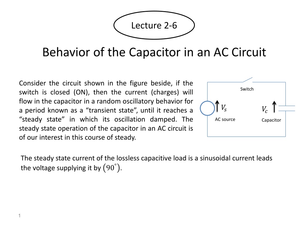
Lecture 2-6 Consider the circuit shown in the figure beside, if the switch is closed (ON), then the current (charges) will flow in the capacitor in a random oscillatory behavior for a period known as a transient state , until it reaches a steady state in which its oscillation damped. The steady state operation of the capacitor in an AC circuit is of our interest in this course of steady. Switch ?? ?? AC source Capacitor The steady state current of the lossless capacitive load is a sinusoidal current leads the voltage supplying it by 90 . 1
To understand the capacitor behavior in AC circuit at steady state, let us start from the first principles: It is already known that by definition: ? = ?? Since, in AC circuit both ? and ? are function of time, then differentiating both sides of the above equation results in: ?? ??= ????? Where ??? is the source voltage supplying the current to the capacitor ? , then: ? ? = ????? ?? ?? Then ????? = ? ? ?? Or ???? =1 ?? ? ?? Integrate both sides results in ? ??? =1 ? ? ? ?? 0 If ??? = ??sin?? Then 2
? ??? =1 ? ??sin ?? ?? 0 ??? =?? ??? = ??cos?? ?? cos ?? 1 ??= ???? Hence Which means that: 1 ??= ?? In a steady state condition of the above circuit, the source voltage [??? ] and the capacitor voltage[??? ]must be equal in magnitude and opposite in polarity always, then this means that the capacitor voltage in this case must be: ??? = ??? = ??cos?? The capacitive reactance ?? represented as a vector of magnitude ?? 90 in order to treat the sinusoidal quantities (voltage or current) using vector algebra. The physical meaning of this representation due to the truth The current passing through a pure capacitance leads the voltage supplying it by 90 . Then, the figure shown below describe the behavior of the capacitor in an AC circuit. 3 and angle
1.5 ?? 1 ?? 0.5 ?? ?? Y-Axis 0 0 5 10 15 20 -0.5 ?? ?? -1 -1.5 Time (ms) AC Source Load Source Source Load Source Source Load Load Capacitor Power ?? ?? ?? ?? ?? ?? ?? ?? ?? ?? ?? ?? From 0 to 90 From 90 to 180 From 180 to 270 From 270 to 360 4
Behavior of the Capacitor in an AC Circuit In DC circuit the capacitor considered as an open circuit at steady-state condition. Hence, no current will circulate in such circuit, but when it supplied by an AC voltage its behavior will be as follows: From ? = ? to ? =? from source to load. From ? =? ? from load to source. From ? =? ? from source to load. From ? =?? ? from load to source, and so on. ? ?: the power transferred ???? to ? =? ? ?: the power transferred 3? 4 to ? =?? ? 4 ?: the power transferred ? 2 to ? = ? : the power transferred ???? 5
Discussion: This behavior of the capacitance means that it will resist the flow of the current during halftime of the cycle (when it considered as a load) and it will assist it to flow during the rest of the time of the cycle (when it considered as a source). Hence, its behavior is not like resistor, and it's not like inductance too, in that its action as a source or as a load occurs at the inverse time periods during the cycle w.r.t. that of the inductance. This means that the steady state current in the capacitor is flowing continuously during the AC cycle and it will never stop as the case in the DC circuit in which the capacitor is considered as an open circuit. The net transferred power equal to zero in a pure capacitive load. 6