Engineering Structural Design Sensitivity Analysis
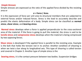
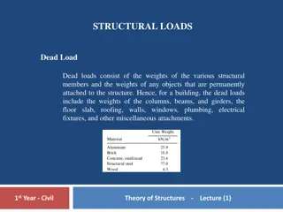
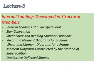
This document presents an overview of structural design sensitivity analysis, including failure strength, knockdown factor, allowable stress, and optimization concepts. It covers topics such as physical engineering problems, performance definition, and model updates in structural analysis. Various design scenarios and constraints are explored through images and diagrams.
Download Presentation

Please find below an Image/Link to download the presentation.
The content on the website is provided AS IS for your information and personal use only. It may not be sold, licensed, or shared on other websites without obtaining consent from the author. Download presentation by click this link. If you encounter any issues during the download, it is possible that the publisher has removed the file from their server.
E N D
Presentation Transcript
160 saverage A-basis 140 120 k s B B-basis 100 80 60 40 20 0 420 440 460 480 500 520 540 560 580 Failure strength (MPa) 6.5 6.0 5.5 5.0 Knockdown factor 4.5 3.41 4.0 3.5 2.36 3.0 1.93 1.78 2.5 2.0 1.5 0 5 10 15 20 25 30 35 40 45 50 Number of coupons L = 100 in h w F = 2,000 lb
y 3 x 2 3 L 1 2 1 L 1,000 N t b b r b r t h h h t w w (a) (b) (c) (d) (e) r Cx Cx r Cy Cy (a) Initial design (b) Perturbed design r r (a) Initial mesh (b) Perturbed mesh
Allowable stress Acceptable region H (dH/db)4 (dH/db)3 (dH/db)2 (dH/db)1 b0b1b2 b3 b4 b Physical engineering problem Structural modeling Design parameterization Performance definition (objective, constraints) Structural analysis (FEM, BEM, CFD ) model update Structural Design sensitivity analysis Optimized? No Yes Stop
w w t1 t1 b t2 h t2 h (a) Independent designs (b) Dependent designs D H Feasible set f(b) b b4 b6 b5 b2 b3 b1 18 f=500 Volume constraint 16 f=400 14 f=300 Feasible set H f=200 12 10 Optimum design 8 3.5 4 4.5 5 5.5 6 6.5 7 7.5 8 D
1 L 1 3 L 2 3 F 2 4 4 3L 2F
b b 1 5 3 2 1 8 10 6 5 b y 9 7 3 4 4 2 x 6 P2 P1
Fx b7 b6 b8 b9 b5 b4 b1 b3 b2 b11 b10 60 kN 2 Pin joint 9 cm Roller support 3 1 12 cm y 1 x 2 3 2 1 2L L F2 F3 p0 = 120 N/m C = 50 N-m 1 2 P C E, I, L
6 5 400 lb 9' 2 3 4 1 12' 12' 12' 1,200 lb A B C RL RR F 0.25 m 0.4 m y 1,500 lb 1 E, I1 2 3 E, I2 x 10 in 25 in p0 E,I,L w t1 t2 h


