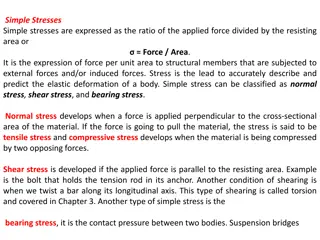
Structural Engineering Solutions: Moments, Stresses, and Centroids

An in-depth analysis of structural engineering problems involving centroids, moments of inertia, maximum stresses, and curvature calculations. Solutions are provided for scenarios such as the application of couples to machine parts and wooden beams, determining maximum tensile and compressive stresses, resolving couple vectors, and finding angles of neutral axes. Formulas for elastic flexural stress and component stress distributions are applied to practical engineering situations.

Download Presentation

Please find below an Image/Link to download the presentation.
The content on the website is provided AS IS for your information and personal use only. It may not be sold, licensed, or shared on other websites without obtaining consent from the author. Download presentation by click this link. If you encounter any issues during the download, it is possible that the publisher has removed the file from their server.
E N D
Presentation Transcript
Exam II-solution 4 problems
SOLUTION: Based on the cross section geometry, calculate the location of the section centroid and moment of inertia. = I A ( ) y A 2 = + Y I A d x Apply the elastic flexural formula to find the maximum tensile and compressive stresses. Mc m= I A cast-iron machine part is acted upon by a 3 kN-m couple. Knowing E = 165 GPa and neglecting the effects of fillets, determine (a) the maximum tensile and compressive stresses, (b) the radius of curvature. Calculate the curvature M = 1 EI 4 - 2
SOLUTION: Based on the cross section geometry, calculate the location of the section centroid and moment of inertia. 2 3 Area, mm mm , mm , A y y 3 = 1 20 90 1800 50 90 10 3 = 2 40 30 A 1200 20 2 4 10 3 = = 3000 114 10 y A 3 114 10 y A = = = 38 mm Y 3000 A ( ) ( ) 2 3 2 1 = + = + Ix I A d bh A d 12 ( ) ( + ) 3 2 3 2 1 1 = + + 90 20 1800 12 30 40 1200 18 12 868 12 3 9 - 4 = 868 = 10 mm 10 m I 4 - 3
Apply the elastic flexural formula to find the maximum tensile and compressive stresses. Mc m = I 3 kN m . 0 022 m M c = + 76 0 . MPa A = = A A 9 4 I 868 10 mm 3 kN m . 0 038 m M c B = 131 3 . MPa = = B B 9 4 I 868 10 mm Calculate the curvature 1 =EI M 1 3 kN m 3 1 - = 20 . 95 10 m )( ) = ( 9 -m 10 4 165 GPa 868 = 47 7 . m 4 - 4
SOLUTION: Resolve the couple vector into components along the principle centroidal axes and calculate the corresponding maximum stresses. cos M M z = = sin M M y Combine the stresses from the component stress distributions. M I y M y y z = + x I A 1600 lb-in couple is applied to a rectangular wooden beam in a plane forming an angle of 30 deg. with the vertical. Determine (a) the maximum stress in the beam, (b) the angle that the neutral axis forms with the horizontal plane. z y Determine the angle of the neutral axis. I z y= z = tan tan I y 4 - 5
Resolve the couple vector into components and calculate the corresponding maximum stresses. ( ) ( ) ( )( ) ( )( ) 9844 . 0 in 5 . 1 in 5 . 3 12 y = = 1600 lb in cos 30 1386 lb in M z = = 1600 lb in sin 30 800 lb in M y 3 4 1 = = 5 . 1 in 5 . 3 in . 5 359 in I z 12 3 4 1 = = in I largest te The M nsile stress due to occurs along M AB z ( )( in ) 1386 lb in . 1 75 4 in y z = = = 452 6 . psi 1 I . 5 359 z largest te The M nsile stress due to occurs along M AD z ( )( ) z 800 lb in . 0 75 4 in y = = = 609 5 . psi 2 I . 0 9844 in y The largest tensile stress due to the combined loading occurs at A. 609 6 . 452 2 1 max + = + = max= 5 . 1062 psi 4 - 6
Determine the angle of the neutral axis. 4 . 5 359 in I z = = tan tan tan 30 4 I . 0 9844 in y = . 3 143 o = 72 4 . 4 - 7
SOLUTION: Determine the horizontal force per unit length or shear flow q on the lower surface of the upper plank. Calculate the corresponding shear force in each nail. A beam is made of three planks, nailed together. Knowing that the spacing between nails is 25 mm and that the vertical shear in the beam is V = 500 N, determine the shear force in each nail. 6 - 8
SOLUTION: Determine the horizontal force per unit length or shear flow q on the lower surface of the upper plank. 6 3 500 ( N 120 )( 10 6 - m ) VQ = = q 4 I 16.20 10 m = Q A y N = 3704 ( . 0 )( ) m = 020 m . 0 100 m . 0 060 m 6 3 = 120 10 m Calculate the corresponding shear force in each nail for a nail spacing of 25 mm. ( . 0 )( ) 3 1 = 020 m . 0 100 m I 12 [ 2 + ( . 0 )( ) 3 1 100 m . 0 020 m 12 020 = = = . 0 ( 025 m ) . 0 ( 025 m 3704 )( F q N m ( . 0 )( ) 2 + m . 0 100 m . 0 060 m ] 92 6 . N F 6 4 = 16 . 20 10 m 6 - 9