Understanding Internal Loadings in Structural Members

Internal loadings in structural members, such as beams and frames, are essential for design. This chapter explores the analysis of shear forces, bending moments, and axial forces, providing methods to determine these forces graphically using shear and moment diagrams. Learn about the sign conventions, methods of finding internal loadings at specified points, and the stress distributions within members for proper design considerations.

Download Presentation

Please find below an Image/Link to download the presentation.
The content on the website is provided AS IS for your information and personal use only. It may not be sold, licensed, or shared on other websites without obtaining consent from the author. Download presentation by click this link. If you encounter any issues during the download, it is possible that the publisher has removed the file from their server.
E N D
Presentation Transcript
Lecture-3 Internal Loadings Developed in Structural Members - Internal Loadings at a Specified Point - Sign Convention - Shear Force and Bending Moment Functions - Shear and Moment Diagrams for a Beam - Shear and Moment Diagrams for a Frame - Moment Diagrams Constructed by the Method of Superposition - Qualitative Deflected Shapes 1
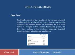
Internal Loadings Developed in Structural Members Unlike trusses, considered in the preceding chapter, whose members are always subjected to only axial forces, the members of rigid frames and beams may be subjected to shear forces and bending moments as well as axial forces under the action of external loads. The determination of these internal forces and moments (stress resultants) is necessary for the design of such structures. The objective of this chapter is to present the analysis of internal forces and moments that may develop in beams, and the members of plane frames, under the action of coplanar systems of external forces and couples. 2
Before a structural member can be proportioned, it is necessary to determine the force and moment that act within it. In this chapter we will develop the methods for finding these loadings at specified points along a member's axis and for showing the variation graphically using the shear and moment diagrams. Applications are given for both beams and frames. 3
The internal load at a specified point in a member can be determined by using the method of sections. In general, this loading for a coplanar structure will consist of a normal force N, shear force V, and bending moment M. It should be realized, however, that these loadings actually represent the resultants of the stress distribution acting over the member's cross-sectional area at the cut section. Once the resultant internal loadings are known, the magnitude of the stress can be determined provided an assumed distribution of stress over the cross-sectional area is specified. 4
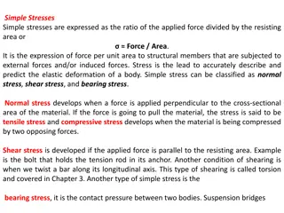
Sign Convention Sign Convention The positive normal force tends to elongate the segment, positive shear tends to rotate the segment clockwise, and positive bending moment tends to bend the segment concave upward, so as to "hold water." 5
Internal loadings at a cross section Internal loadings at a cross section P w A B x A B y A y w Pw MV M x A N V w w B y A y +y Sign +x + - Convention Coordinates 6
Example Example w w Sign + - Convention 7
The design of a beam requires a detailed knowledge of the variations of the internal shear force V and moment M acting at each point along the axis of the beam. The internal normal force is generally not considered for two reasons: (1) in most cases the loads applied to a beam act perpendicular to the beam's axis and hence produce only an internal shear force and bending moment, and (2) for design purposes the beam's resistance to shear, and particularly to bending, is more important than its ability to resist normal force. An important exception to this occurs, however, when beams are subjected to compressive axial forces, since the buckling or instability that may occur has to be investigated. 8
The variations of V and M as a function of the position x of an arbitrary point along the beam's axis can be obtained by using the method of sections discussed in previous section. Here, however, it is necessary to locate the imaginary section or cut at an arbitrary distance xfrom one end of the beam rather than at a specific point. 9
Force, Shear and Bending Moment Force, Shear and Bending Moment w dV= w V dx M+dM M + dM= V dx V+dV dx w P D D = = dV V V wdx D C C C B A D D = = dM M M Vdx C D D C VD VC C C 10
Force, Shear and Bending Moment Force, Shear and Bending Moment P P V V x V-P Shear force moves toward negative direction Mo V-P dx Mo M M M-Mo x + M-Mo Moment moves toward Negative direction dx 11
Shear Force & Bending Moment Diagram Shear Force & Bending Moment Diagram P L/2 L/2 dV= w B A dx dM= V +P/2 dx V 2 M= d y -P/2 2 EI dx +PL/4 M = curvature EI +M M -M Need to know deflection shape qualitatively 12
Shear Force & Bending Moment Diagram Shear Force & Bending Moment Diagram Structure under loads dV= w Slope of V = load dx Shear force diagram dM= Slope of M = V V dx Bending moment diagram 2 M= d y 2 EI dx Qualitative deflection shape Bending moment diagram (plotted on the compression side) 13
Shear & Moment Diagrams for a Beam Shear & Moment Diagrams for a Beam Sign Convention w + w - dV= w dx dM= V dx 14
Example Example 15
PROCEDURE FOR ANALYSIS PROCEDURE FOR ANALYSIS Support Reactions Before the member is "cut" or sectioned, it may be necessary to determine the member's support reactions so that the equilibrium equations are used only to solve for the internal loadings when the member is sectioned. If the member is part of a pin-connected structure, the pin reactions can be determined using the equations of equilibrium. 16
Free-Body Diagram Keep all distributed loadings, couple moments, and forces acting on the member in their exact location, then pass an imaginary section through the member, perpendicular to its axis at the point where the internal loading is to be determined. After the section is made, draw a free-body diagram of the segment that has the least number of loads on it. At the section indicate the unknown resultants N, V, and M acting in their positive directions. 17
Equations of Equilibrium Moments should be summed at the section about axes that pass through the centroid of the member's cross-sectional area, in order to eliminate the unknowns N and V and thereby obtain a direct solution for M. If the solution of the equilibrium equations yields a quantity having a negative magnitude, the assumed directional sense of the quantity is opposite to that shown on the free-body diagram. 18
Shear and Moment Functions The horizontal members on this power line support frame were designed once the shear and moment within the members were established. Specify separate coordinates x and associated origins, extending into regions of the beam between concentrated forces and/or couple moments, or where there is a discontinuity of distributed loading. Section the beam perpendicular to its axis at each distance x, and from the free-body diagram of one of the segments determine the unknowns V and M at the cut section as functions of x. On the free- body diagram, V and M should be shown acting in their positive directions, in accordance with the sign convention given in Fig. 4-1. V is obtained from Fy= 0 and M is obtained by summing moments about the point S located at the cut section, MS = 0. The results can be checked by noting that dM/dx = V and dV/dx = w, where w is positive when it acts upward, away from the beam. These relationships are developed in next Sec. 19
Since beams are used primarily to resist bending stress, it is important that the moment diagram accompany the solution for their design. In previous Sec. the moment diagram was constructed by first drawing the shear diagram. If we use the principle of superposition, however, each of the loads on the beam can be treated separately and the moment diagram can then be constructed in a series of parts rather than a single and sometimes complicated shape. It will be shown later in the text that this can be particularly advantageous when applying geometric deflection methods to determine both the deflection of a beam and the reactions on statically indeterminate beams. 20
Software 22
Example Example Draw shear force and bending moment diagrams 23
Solution Solution 9m Anticlockw moment ise as - ve : = 0 V = 0 Ms 1 20 1 . 5 20 . 5 20 + = = + + = 0 30 0 F x x 30 . 5 ( 20 ) 20 . 5 20 0 M y 2 9 2 9 3 24 = 104 M kNm = 20 . 5 x m
QUALITATIVE DEFLECTED SHAPES A qualitative deflected shape (elastic curve) of a structure is simply a rough (usually exaggerated) sketch of the neutral surface of the structure, in the deformed position, under the action of a given loading condition. According to the sign convention, a positive bending moment bends a beam concave upward (or toward the positive y direction), whereas a negative bending moment bends a beam concave downward (or toward the negative y direction). Thus, the sign (positive or negative) of the curvature at any point along the axis of a beam can be obtained from the bending moment diagram. 25
2 2 hinges hinges 31
3 3 hinges hinges 32
Closed Loop 33