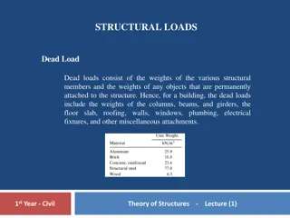
Understanding Simple Stresses in Structural Engineering

Simple stresses play a crucial role in structural analysis by determining the force per unit area on structural members. Normal, shear, and bearing stresses are key classifications that describe the behavior of materials under external forces. This article delves into the concepts of simple stresses, their applications, and practical examples like suspension bridges to showcase the importance of stress analysis in engineering.

Download Presentation

Please find below an Image/Link to download the presentation.
The content on the website is provided AS IS for your information and personal use only. It may not be sold, licensed, or shared on other websites without obtaining consent from the author. Download presentation by click this link. If you encounter any issues during the download, it is possible that the publisher has removed the file from their server.
E N D
Presentation Transcript
Simple Stresses Simple stresses are expressed as the ratio of the applied force divided by the resisting area or = Force / Area. It is the expression of force per unit area to structural members that are subjected to external forces and/or induced forces. Stress is the lead to accurately describe and predict the elastic deformation of a body. Simple stress can be classified as normal stress, shear stress, and bearing stress. Normal stress develops when a force is applied perpendicular to the cross-sectional area of the material. If the force is going to pull the material, the stress is said to be tensile stress and compressive stress develops when the material is being compressed by two opposing forces. Shear stress is developed if the applied force is parallel to the resisting area. Example is the bolt that holds the tension rod in its anchor. Another condition of shearing is when we twist a bar along its longitudinal axis. This type of shearing is called torsion and covered in Chapter 3. Another type of simple stress is the bearing stress, it is the contact pressure between two bodies. Suspension bridges
Suspension bridges are good example of structures that carry these stresses. The weight of the vehicle is carried by the bridge deck and passes the force to the stringers (vertical cables), which in turn, supported by the main suspension cables. The suspension cables then transferred the force into bridge towers.
Normal Stress Stress Stress is the expression of force applied to a unit area of surface. It is measured in psi (English unit) or in MPa (SI unit). Another unit of stress which is not commonly used is the dynes (cgs unit). Stress is the ratio of force over area. stress = force / area Simple Stresses There are three types of simple stress namely; normal stress, shearing stress, and bearing stress. Normal Stress The resisting area is perpendicular to the applied force, thus normal. There are two types of normal stresses; tensile stress and compressive stress. Tensile stress applied to bar tends the bar to elongate while compressive stress tend to shorten the bar. where P is the applied normal load in Newton and A is the area in mm2. The maximum stress in tension or compression occurs over a section normal to the load
A hollow steel tube with an inside diameter of 100 mm must carry a tensile load of 400 kN. Determine the outside diameter of the tube if the stress is limited to 120 MN/m2.
A homogeneous 800 kg bar AB is supported at either end by a cable as shown in Fig Calculate the smallest area of each cable if the stress is not to exceed 90 MPa in bronze and 120 MPa in steel
The homogeneous bar shown in Fig. is supported by a smooth pin at C and a cable that runs from A to B around the smooth peg at D. Find the stress in the cable if its diameter is 0.6 inch and the bar weighs 6000 lb.
A rod is composed of an aluminum section rigidly attached between steel and bronze sections, as shown in Fig. P-107. Axial loads are applied at the positions indicated. If P = 3000 lb and the cross sectional area of the rod is 0.5 in2, determine the stress in each section.
An aluminum rod is rigidly attached between a steel rod and a bronze rod as shown in Fig. P-108. Axial loads are applied at the positions indicated. Find the maximum value of P that will not exceed a stress in steel of 140 MPa, in aluminum of 90 MPa, or in bronze of 100 MPa.
Determine the largest weight W that can be supported by two wires shown in Fig. P-109. The stress in either wire is not to exceed 30 ksi. The cross-sectional areas of wires AB and AC are 0.4 in2 and 0.5 in2, respectively
The homogeneous bar ABCD shown in Fig. P-114 is supported by a cable that runs from A to B around the smooth peg at E, a vertical cable at C, and a smooth inclined surface at D. Determine the mass of the heaviest bar that can be supported if the stress in each cable is limited to 100 MPa. The area of the cable AB is 250 mm2 and that of the cable at C is 300 mm2.
Shearing Stress Forces parallel to the area resisting the force cause shearing stress. It differs to tensile and compressive stresses, which are caused by forces perpendicular to the area on which they act. Shearing stress is also known as tangential stress. where V is the resultant shearing force which passes which passes through the centroid of the area A being sheared.
What force is required to punch a 20-mm-diameter hole in a plate that is 25 mm thick? The shear strength is 350 MN/m2.
Find the smallest diameter bolt that can be used in the clevis shown in Fig. below if P = 400 kN. The shearing strength of the bolt is 300 MPa.
Compute the shearing stress in the pin at B for the member supported as shown in Fig. below. The pin diameter is 20 mm.
Bearing Stress Bearing stress is the contact pressure between the separate bodies. It differs from compressive stress, as it is an internal stress caused by compressive forces.
In Fig. below, assume that a 20-mm-diameter rivet joins the plates that are each 110 mm wide. The allowable stresses are 120 MPa for bearing in the plate material and 60 MPa for shearing of rivet. Determine (a) the minimum thickness of each plate; and (b) the largest average tensile stress in the plates.
The lap joint shown in Fig. P-126 is fastened by four -in.-diameter rivets. Calculate the maximum safe load P that can be applied if the shearing stress in the rivets is limited to 14 ksi and the bearing stress in the plates is limited to 18 ksi. Assume the applied load is uniformly distributed among the four rivets.
In the clevis shown in Fig. 1-11b, find the minimum bolt diameter and the minimum thickness of each yoke that will support a load P = 14 kips without exceeding a shearing stress of 12 ksi and a bearing stress of 20 ksi.