Understanding Transient Behavior in Electrical Systems
Explore the transient behavior in electrical systems through a series of zoomed-in and zoomed-out images depicting different stages during power transitions. Follow along as signals oscillate, square shapes are lost, and switches are cycled, offering insights into system behavior under various conditions.

Download Presentation

Please find below an Image/Link to download the presentation.
The content on the website is provided AS IS for your information and personal use only. It may not be sold, licensed, or shared on other websites without obtaining consent from the author. Download presentation by click this link. If you encounter any issues during the download, it is possible that the publisher has removed the file from their server.
E N D
Presentation Transcript
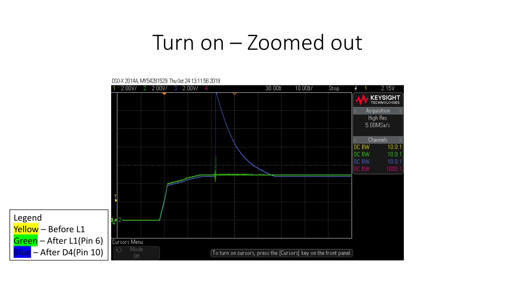
Turn on Zoomed out Legend Yellow Before L1 Green After L1(Pin 6) Blue After D4(Pin 10)
Turn on Transient zoomed in Legend Yellow Before L1 Green After L1(Pin 6) Blue After D4(Pin 10)
Turn on Transient zoomed in Switching waveform starts to lose square shape Legend Yellow Before L1 Green After L1(Pin 6) Blue After D4(Pin 10)
Turn Off Legend Yellow Before L1 Green After L1(Pin 6) Blue After D4(Pin 10)
Turn on Transient zoomed in Z1 removed Legend Yellow Before L1 Green After L1(Pin 6) Blue After D4(Pin 10)
Turn on Transient zoomed in Z1 removed - All 3 signals start to oscillate Legend Yellow Before L1 Green After L1(Pin 6) Blue After D4(Pin 10)
Turn on Transient zoomed in - Z1 removed Switching stops Legend Yellow Before L1 Green After L1(Pin 6) Blue After D4(Pin 10)
Turn Z1 removed Legend Yellow Before L1 Green After L1(Pin 6) Blue After D4(Pin 10)
Turn on Transient zoomed in cycled fault reset pin Legend Yellow Before L1 Green After L1(Pin 6) Blue After D4(Pin 10)
Turn on Transient zoomed in on switching waveforms - cycled fault reset pin Legend Yellow Before L1 Green After L1(Pin 6) Blue After D4(Pin 10)
Turn on Transient zoomed in switching stops - cycled fault reset pin Legend Yellow Before L1 Green After L1(Pin 6) Blue After D4(Pin 10)
Notes Notes D4 removed and measured voltage drop 0.175 Instability of signals starts to appear without Z1 in place Inductor removed and measured 56uH When toggling the fault reset pin, faults that appear are FOSHORT, OMIZ1H, OMIZ3H Connected to a different resolver than the one used for the skyjack project. Uses same base configuration settings 4 pole pair, 10KHz, 7V. Switching signal does not appear the same as screenshots taken at AMD. Signal looks more square like it should be.