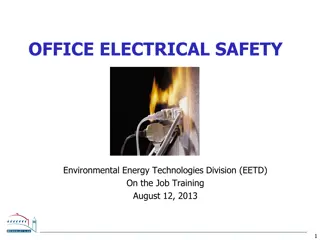
Understanding Overvoltages and Lightning Phenomena in Electrical Systems

Overvoltages in electrical systems can be caused by internal or external factors, leading to potential damage if not properly managed. This article explores the types of overvoltages, their causes, and the importance of designing high-voltage insulation systems. Additionally, the historical significance of Benjamin Franklin's kite experiment in understanding the electrical nature of lightning is highlighted.

Download Presentation

Please find below an Image/Link to download the presentation.
The content on the website is provided AS IS for your information and personal use only. It may not be sold, licensed, or shared on other websites without obtaining consent from the author. Download presentation by click this link. If you encounter any issues during the download, it is possible that the publisher has removed the file from their server.
E N D
Presentation Transcript
OVER VOLTAGES Increase in voltage for very short time Also Called as voltage surge or voltage transients Causes: 1. Over voltage due to external causes 2. Over voltage due to internal causes DEPARTMENT OF EEE/BSA CRESCENT IS & T
OVER VOLTAGE DUE TO INTERNAL CAUSES by connecting or disconnecting the system or due to the systems fault initiation or extinction Temporary overvoltages: if they are oscillatory of power frequency or harmonics under no load or very light load conditions Switching overvoltages: if they are heavily damped and of short duration Both types occur together , because of their nature => Design of HV insulation system DEPARTMENT OF EEE/BSA CRESCENT IS & T
OVER VOLTAGE DUE TO INTERNAL CAUSES ctd., overvoltages increases with increasing the operating voltage of the system with increasing the system s operating voltage a point is reached when the switching overvoltages become the dominant factor in designing the system s insulation DEPARTMENT OF EEE/BSA CRESCENT IS & T
OVER VOLTAGE DUE TO EXTERNAL CAUSES lightning strokes in the cloud independent of the system s design Insulation design depends on Upto 300kV primarily lightning surges 300 kV to 765 kV both lightning and switching surges Above 765 kV switching overvoltages in combination with insulator contamination DEPARTMENT OF EEE/BSA CRESCENT IS & T
KITE EXPERIMENT Benjamin Franklin (1752) and his experiments, in which were demonstrated the electrical nature of lightning DEPARTMENT OF EEE/BSA CRESCENT IS & T
KITE EXPERIMENT such dangerous experiments were stopped after the tragical death of Prof. Richmann (1753) serious explanations of lightning phenomena exist until the 19th/ 20th century The real incentive to study lightning came when electric transmission lines had to be protected against lightning DEPARTMENT OF EEE/BSA CRESCENT IS & T
TYPES OF LIGHTNING Intra- Cloud(s) (IC) Cloud- Ground (CG) Ground- Cloud (5%) Cloud- Ground (95%) DEPARTMENT OF EEE/BSA CRESCENT IS & T
MEASUREMENTS CONSIDERED FOR STUDY (i) lightning current (ii) magnetic and electromagnetic radiated fields (iii) voltages (iv) use of high-speed photography and radar DEPARTMENT OF EEE/BSA CRESCENT IS & T
PHENOMENA THUNDER CLOUDS 1.The height of the cloud base above the surrounding ground level may vary from 160 to 9,500 m. The charged centres which are responsible for lightning are in the range of 300 to 1500 m. 2. The maximum charge on a cloud is of the order of 10 C which is built up exponentially over a period of perhaps many seconds or even minutes. 3. The maximum potential of a cloud lies approximately within the range of 10 MV to 100 MV. 4. The energy in a lightning stroke may be of the order of 250 kWhr. DEPARTMENT OF EEE/BSA CRESCENT IS & T
PHENOMENA THUNDER CLOUDS 5. Raindrops: (a) Raindrops elongate and become unstable under an electric field, the limiting diameter being 0.3 cm in a field of 100 kV/cm. (b) A free falling raindrop attains a constant velocity with respect to the air depending upon its size. 800 cm/sec for drops of the size 0.25 cm diameter zero for spray This means that in case the air currents are moving upwards with a velocity greater than 800 cm/sec, no rain drop can fall. (c) Falling raindrops greater than 0.5 cm in diameter become unstable and break up into smaller drops. DEPARTMENT OF EEE/BSA CRESCENT IS & T
WATER DROP ICE CRYSTAL - + - + - + - + - + Air current Air current (d) When a drop is broken up by air currents, the water particles become positively charged and the air negatively charged. (e) When an ice crystal strikes with air currents, the ice crystal is negatively charged and the air positively charged. DEPARTMENT OF EEE/BSA CRESCENT IS & T
WILSONS THEORY OF CHARGE SEPARATION DEPARTMENT OF EEE/BSA CRESCENT IS & T
wilsons theory of charge separation ctd., assumption that a large number of ions are present in the atmosphere ions attach themselves to small dust particles and water particles electric field exists in the earth s atmosphere during fair weather which is directed downwards towards the earth The intensity of the field is approximately 1 volt/cm at the surface of the earth and decreases gradually with height so that at 9,500 m it is only about 0.02 V/cm DEPARTMENT OF EEE/BSA CRESCENT IS & T
wilsons theory of charge separation ctd., DEPARTMENT OF EEE/BSA CRESCENT IS & T
SIMPSONS AND SCARSE THEORY based on the temperature variations in the various regions of the cloud. DEPARTMENT OF EEE/BSA CRESCENT IS & T
MECHANISM OF LIGHTNING STROKE Lightning phenomenon is the discharge of the cloud to the ground DEPARTMENT OF EEE/BSA CRESCENT IS & T
LINE DESIGN BASED ON LIGHTNING Lightning creates magnetically induced current in all metal items within its influence The longer the wire, greater the current The closer the strike, greater the current Any impedance to current flow results in Build up of high voltage at that location Resulting in arc-over to reach ground Ignites flammable material Vaporizes metal of insufficient cross-section DEPARTMENT OF EEE/BSA CRESCENT IS & T
SWITCHING SURGE TEST VOLTAGE CHARACTERISTICS DEPARTMENT OF EEE/BSA CRESCENT IS & T
INTRODUCTION Transmission voltage : 220 kV and below Over voltage due to lightning were of high order Over voltage generated inside the system were less Transmission voltage : 400 kV and above The overvoltages generated inside the system reached the same order of magnitude as those of lightning over voltages, or higher. The overvoltages thus generated last for longer durations and therefore are severe and more dangerous to the system. DEPARTMENT OF EEE/BSA CRESCENT IS & T
INSULATION CO-ORDINATION The protective level of any particular kind of surge diverter is proportional to the maximum voltage the insulation level The cost of the equipment depends on the magnitudes of these overvoltages DEPARTMENT OF EEE/BSA CRESCENT IS & T
ORIGIN OF SWITCHING SURGES Power systems have large inductances and capacitances Making and breaking of electric circuits with switchgear may result in abnormal overvoltages Overvoltages = 6 times of normal power frequency voltage. switching surges with a high rate of rise of voltage may cause repeated restriking of the arc between the contacts of a circuit breaker, thereby causing destruction of the circuit breaker contacts. high natural frequencies of the system a damped normal frequency voltage component, the restriking recovery voltage of the system with successive reflected waves from terminations. DEPARTMENT OF EEE/BSA CRESCENT IS & T
CHARACTERISTICS OF SWITCHING SURGES De-energizing of transmission lines, cables, shunt capacitor, banks, etc. Disconnection of unloaded transformers, reactors, etc. Energization or reclosing of lines and reactive loads, Sudden switching off of loads. Short circuits and fault clearances. Resonance phenomenon like grounds, etc. ferro-resonance, arcing DEPARTMENT OF EEE/BSA CRESCENT IS & T
TYPICAL WAVESHAPES OF SWITCHING SURGE VOLTAGES Recovery voltage after fault clearing Fault initiation DEPARTMENT OF EEE/BSA CRESCENT IS & T
TYPICAL WAVESHAPES OF SWITCHING SURGE VOLTAGES Overvoltage at the line end after Energization of long transmission line fault clearing DEPARTMENT OF EEE/BSA CRESCENT IS & T
Overvoltage at line end during energization of long transmission line TYPICAL WAVESHAPES OF SWITCHING SURGE VOLTAGES DEPARTMENT OF EEE/BSA CRESCENT IS & T
overvoltages are irregular (oscillatory or unipolar) and of high frequency or power frequency with its harmonics The relative magnitudes of the overvoltages may be about 2.4 p.u. in the case of transformer energizing 1.4 to 2.0 p.u. in switching transmission lines DEPARTMENT OF EEE/BSA CRESCENT IS & T
SWITCHING OVERVOLTAGES IN EHV AND UHV SYSTEMS The insulation has the lowest strength for switching surges with regard to long air gaps. switching overvoltages are of relatively higher magnitudes as compared to the lightning overvoltages for UHV systems interruption of low inductive currents (current chopping) by high speed circuit breakers. This occurs when the transformers or reactors are switched off interruption of small capacitive currents, such as switching off of unloaded lines etc. ferro-resonance condition - This may occur when poles of a circuit breaker do not close simultaneously energization of long EHV or UHV lines. DEPARTMENT OF EEE/BSA CRESCENT IS & T
SWITCHING OVERVOLTAGES IN EHV AND UHV SYSTEMS Transient overvoltages will have magnitudes of the order of 1200 kV to 2000 kV on 750 kV systems. Duration:1 to 10ms These magnitudes will be higher during lightning and last for several cycles DEPARTMENT OF EEE/BSA CRESCENT IS & T
SWITCHING OVERVOLTAGES IN EHV AND UHV SYSTEMS switching overvoltages of shorter duration (0.5 to 5 ms) and lower magnitudes (2.0 to 2.5 p.u.)are due to (a) single pole closing of circuit breaker (b) interruption of fault current when the L-G or L-L fault is cleared (c) resistance switching used in circuit breakers (d) switching lines terminated by transformers (e) series capacitor compensated lines (f) sparking of the surge diverter located at the receiving end of the line to limit the lightning overvoltages DEPARTMENT OF EEE/BSA CRESCENT IS & T
SWITCHING OVERVOLTAGES IN EHV AND UHV SYSTEMS The overvoltages due to the above conditions are studied or calculated from (a) mathematical modelling of a system using digital computers (b) scale modelling using transient network analysers (c) by conducting field tests to determine the expected maximum amplitude of the overvoltages and their duration at different points on the line. DEPARTMENT OF EEE/BSA CRESCENT IS & T
SWITCHING OVERVOLTAGES IN EHV AND UHV SYSTEMS The main factors that are investigated (i) the effect of line parameters, series capacitors and shunt reactors on the magnitude and duration of the transients (ii) the damping factors needed to reduce the magnitude of overvoltages (iii) the effect of single pole closing, restriking and switching with series resistors or circuit breakers on the overvoltages, and (iv) the lightning arrester sparkover characteristics.It DEPARTMENT OF EEE/BSA CRESCENT IS & T
SWITCHING OVERVOLTAGES IN EHV AND UHV SYSTEMS The measures taken to control or reduce the overvoltages are (i) one step or multi-step energization of lines by pre-insertion of resistors, (ii) phase controlled closing of circuit breakers with proper sensors, (iii) drainage of trapped charges on long lines before the reclosing of the lines,and (iv) limiting the overvoltages by using surge diverters. DEPARTMENT OF EEE/BSA CRESCENT IS & T
POWER FREQUENCY OVERVOLTAGES IN POWER SYSTEMS DEPARTMENT OF EEE/BSA CRESCENT IS & T
The power frequency overvoltages occur in large power systems and they are of much concern in EHV systems, i.e. systems of 400 kV and above. The main causes for power frequency and its harmonic overvoltages are (a) sudden loss of loads, (b) disconnection of inductive loads or connection of capacitive loads, (c) Ferranti effect, unsymmetrical faults, and (d) saturation in transformers, etc. Overvoltages of power frequency harmonics and voltages with frequencies nearer to the operating frequency are caused during tap changing operations, by magnetic or ferro-resonance phenomenon in large power transformers, and by resonating overvoltages due to series capacitors with shunt reactors or transformers. DEPARTMENT OF EEE/BSA CRESCENT IS & T
Sudden load rejection on large power systems causes the speeding up of generator prime movers SUDDEN LOAD REJECTION The speed governors and automatic voltage regulators will intervene to restore normal conditions But initially both the frequency and voltage increase. The approximate voltage rise, neglecting losses, etc. may be taken as xs = reactance of the generator ( the sum of the transient reactances of the generator and the transformer) xc = capacitive reactance of the line at open end at increased frequency E = voltage generated before the over-speeding and load rejection f = the instantaneous increased frequency fo= is the normal frequency DEPARTMENT OF EEE/BSA CRESCENT IS & T
This increase in voltage may go to as high as 2.0 per unit (p.u.) value with 400 kV lines. The voltage at the sending end is affected by the line length, short circuit MVA at sending end bus, and reactive power generation of the line (due to line capacitive reactance and any shunt or series capacitors). Shunt reactors may reduce the voltage to 1.2 to 1.4 p.u. DEPARTMENT OF EEE/BSA CRESCENT IS & T
Long uncompensated lines exhibit voltage rise at receiving end V2=V1/cos l Where V1, V2 are the sending and receiving end voltages respectively FERRANTI EFFECT l=length of the line =Phase constant of the line = [(R+j L) (G+j C)/LC]1/2 =6 degree per 100 km line at 50 Hz frequency =Angular frequency DEPARTMENT OF EEE/BSA CRESCENT IS & T
APPROXIMATED SOLUTION Capacitance is concentrated in middle Solution yields DEPARTMENT OF EEE/BSA CRESCENT IS & T
SLTG cause rise in voltage in other healthy phases GROUND FAULTS AND THEIR EFFECTS Solid ground systems, voltage rise is less than the line to line voltage Effectively ground systems, X0/X1< 3.0 and R0/X1 < 1.0 rise in voltage of healthy phases does not usually exceed 1.4 pu DEPARTMENT OF EEE/BSA CRESCENT IS & T
SATURATION EFFECTS When overvoltage(OV) is applied to transformers, their magnetizing currents increase rapidly, It may be about full rated current for 50% overvoltage These are not sinusoidal but peaky waveform 3rd,5th and 7th harmonics be 65%,35%,and 25% of rated current with fundamental frequency to OV of 1.2 pu DEPARTMENT OF EEE/BSA CRESCENT IS & T
SATURATION EFFECTS Zero sequence impedance is effective Delta connected windings will suppress them 3rd and multiple harmonics Series resonance between transformer L and line C occurs Higher voltage is produced Higher harmonics DEPARTMENT OF EEE/BSA CRESCENT IS & T
CONTROL OF OVERVOLTAGES DUE TO SWITCHING DEPARTMENT OF EEE/BSA CRESCENT IS & T
The overvoltages due to switching and power frequency may be controlled by (a) energization of transmission lines in one or more steps by inserting resistances and withdrawing them afterwards, (b) phase controlled closing of circuit breakers, (c) drainage of trapped charges before reclosing, (d) use of shunt reactors, and (e) limiting switching surges by suitable surge diverters. DEPARTMENT OF EEE/BSA CRESCENT IS & T
INSERTION OF RESISTORS common practice to insert resistances R in series with circuit breaker contacts when switching on but short circuiting them after a few cycles. reduce the transients occurring due to switching Zo/(R+Zo) per unit The voltage step is reduced to this value (R-Zo)/(R+Zo) Reflection factor per unit R = Zo No reflection The applied step at the first instance is only 0.5 per unit DEPARTMENT OF EEE/BSA CRESCENT IS & T
Insertion of Resistors ctd., When circuited, a voltage step equal to the instantaneous voltage drop enters the line. the resistor is short But for conventional opening of the breaker, the resistors have too high an ohmic value to be effective for resistance closing. If the resistor is kept for a duration larger than 5ms (for50 Hz sine wave duration). Therefore, suitable practice is done to limit the overvoltage to less than 2.0 to 2.5 p.u. re-insertion value of in resistors = 1/4 cycle It can be shown from successive reflections and transmissions, that the overvoltage may reach as high as 1.2 p.u. for a line length of 500 km. Normal time of insertion is 6 to 10 m s. DEPARTMENT OF EEE/BSA CRESCENT IS & T
PHASE CONTROLLED SWITCHING Overvoltages can be avoided by controlling the exact instances of the closing of the three phases separately. But this necessitates the use of complicated controlling equipment and therefore is not adopted. DEPARTMENT OF EEE/BSA CRESCENT IS & T


 and")