Understanding Time Domain Dynamic Responses in Control Systems
In the field of control systems, analyzing time domain dynamic responses is essential for evaluating system performance. This involves studying transient and steady-state responses, as well as characteristics such as steady-state error. By examining these responses to standard input signals, insights into system behavior and specifications can be gained. The time response of a control system can provide valuable information for system identification and modeling.

Download Presentation

Please find below an Image/Link to download the presentation.
The content on the website is provided AS IS for your information and personal use only. It may not be sold, licensed, or shared on other websites without obtaining consent from the author. Download presentation by click this link. If you encounter any issues during the download, it is possible that the publisher has removed the file from their server.
E N D
Presentation Transcript
- Control In Processes and Systems (5) Dr. Enas Ismail E-mail: enas.ismail@mu.edu.eg Whats-up: 01021240082 - 2020-2019
Time Domain System Dynamic Response
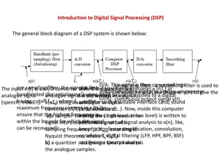
Time domain dynamic response (1) Because time is used as an independent variable in most control systems, it is usually of interest to evaluate the state and output responses with respect to time or, simply, the time response. In the analysis problem, a reference input signal is applied to a system, and the performance of the system is evaluated by studying the system response in the time domain. Time response: is the response given by the system which is function of the time to applied excitation.
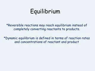
Time domain dynamic response (2) The time response of a control system is usually divided into two parts: the transient response and the steady-state response. ??(t): transient response is defined as the part of the time response that goes to zero as time becomes very large. ???(t):The steady-state response is simply the part of the total response that remains after the transient has died out. (final accuracy of the system) All real, stable control systems exhibit transient phenomena to some extent before the steady state is reached
Time domain dynamic response (3) Steady state error: it is the difference between the desired output and actual output (reference input) at infinite time or at steady state. ess=lim t (r(t)-c(t)) Where : r(t) desired output c(t) Actual output
Time domain dynamic response (4) Advantages of studying time dynamic response: - Classifying the response of some standard systems to standard inputs can provide an insight into more complicated systems. o Ex system: first order second order o Ex inputs: unit- ramp- sinusoid - Time domain standard Characteristics of a standard dynamic response can be used for inferring system specifications. - Response to simple inputs can be used for system identification, i.e. for black box modeling.
Time Domain System Dynamic Response Transient and Steady-State Dynamic Response Analyses - Standard input signals - standard Time dynamic response characteristics (Standard First order control system) (Standard second-order control system) - Steady state error analysis OGATA ch.5
Standard Input Signals TYPICAL TEST SIGNALS FOR THE TIME RESPONSE OF CONTROL SYSTEMS automatic control system(KOO) ch.5 pg.254
TYPICAL TEST SIGNALS FOR THE TIME RESPONSE OF CONTROL SYSTEMS Unlike electric networks and communication systems, the inputs to many practical control systems are not exactly known ahead of time. This poses a problem for the designer, because it is difficult to design a control system so that it will perform satisfactorily to all possible forms of input signals. For the purpose of analysis and design, it is necessary to assume some basic types of test inputs so that the performance of a system can be evaluated. By selecting these basic test signals properly, not only is the mathematical treatment of the problem systematized, but the response due to these inputs allows the prediction of the system's performance to other more complex inputs. To facilitate the time-domain analysis, the following deterministic test signals are used. automatic control system(KOO) ch.5 pg.254
Name Mathematical formula Time-domain shape Advantage - Tests system's quickness in responding to inputs with abrupt changes. Step - instantaneous change in the reference input. - application of numerous sinusoidal signals with a wide range of frequencies - its initial instantaneous jump in amplitude. Ramp - changes constantly with time. Parabolic - tests how the system would respond to a signal that changes linearly with time. - one order faster than the ramp function.
Standard Time dynamic response characteristics (Standard First order control system) (Standard second-order control system) System Order / Type
System Order / Type (1) Input-output relation: 1. Differential Equation : order of the system is the higher power of the diff. Eq. 2. Transfer Function (Three Forms): 1. Polynomials 2. pole-zero form 3. time constant form
System Representation 2. Time-constant form
System Order & Type (2) Forward-Path transfer function G(s) System order : number of poles of the system (order of system differential equation. System type: Number of poles at origin s=0.
System Order & Type (3) Example
Unit step Response Unit Ramp Response Unit parabolic response
Time-domain dynamic response First-order system Important Notes: Unit impulse response - The step input yields the desired information about the speed of transient response. It is observed that the speed of response is inversely proportional to the time constant r of the system. The ramp and parabolic inputs do not give any additional information regarding the speed of response. (derivatives into step response) However, the steady state errors are different for these three different inputs. For a step input, the steady state error ess is zero, for a velocity input there is a finite error equal to the time constant of the system and for an acceleration input the steady state error is infinity. - - e(t)=1-c(t) at t= , e(t)=1 - - -
Transient response specifications of second-order control system (1)
Transient response specifications of second-order control system (2)
Transient response specifications of second-order control system (3)
Transient response specifications of second-order control system (4)
Transient response specifications of second-order control system (5)
Steady state response specifications of second-order control system (6)


")
")
")
")


")


")
")
")
")
")
")
")