Understanding Faults in Electrical Systems
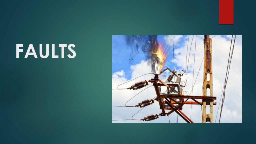
In electrical systems, faults are barriers that disrupt the flow of current, leading to abnormal conditions like short circuits or open circuits. Faults can cause harm to equipment and personnel, affecting system operation and creating safety hazards. Common types of faults include open circuit faults and short circuit faults, each with specific causes and effects on the electrical network. Recognizing and addressing faults promptly is crucial to maintaining system reliability and preventing damage.

Download Presentation

Please find below an Image/Link to download the presentation.
The content on the website is provided AS IS for your information and personal use only. It may not be sold, licensed, or shared on other websites without obtaining consent from the author. Download presentation by click this link. If you encounter any issues during the download, it is possible that the publisher has removed the file from their server.
E N D
Presentation Transcript
What is Fault ? In electrical system a fault is a barrier in path of flow of current. For example short circuit is a fault in which current bypass the normal load. Electrical networks, machines and equipment's are often subjected to various types of faults while they are in operation. When a fault occurs, the characteristic values (such as impedance) of the machines may change from existing values to different values till the fault is cleared. There are different types of faults in electrical systems which are given like that : 1. Open circuit Fault 2. Short circuit Fault 3. Symmetrical Faults 4. Unsymmetrical Faults
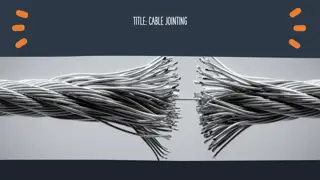
Open Circult faults : These faults occur due to the failure of one or more conductors. The figure below illustrates the open circuit faults for single, two and three phases (or conductors) open condition. The most common causes of these faults include joint failures of cables and overhead lines, and failure of one or more phase of circuit breaker and also due to melting of a fuse or conductor in one or more phases. Open circuit faults are also called as series faults. These are unsymmetrical or unbalanced type of faults except three phase open fault.
Causes and effects : Causes : Broken conductor and malfunctioning of circuit breaker in one or more phases Effects Abnormal operation of the system Danger to the personnel as well as animals Exceeding the voltages beyond normal values in certain parts of the network, which further leads to insulation failures and developing of short circuit faults.
Short Circuit Faults A short circuit can be defined as an abnormal connection of very low impedance between two points of different potential, whether made intentionally or accidentally. These are the most common and severe kind of faults, resulting in the flow of abnormal high currents through the equipment or transmission lines. If these faults are allowed to persist even for a short period, it leads to the extensive damage to the equipment. Short circuit faults are also called as shunt faults. These faults are caused due to the insulation failure between phase conductors or between earth and phase conductors or both. The various possible short circuit fault conditions include three phase to earth, three phase clear of earth, phase to phase, single phase to earth, two phase to earth and phase to phase plus single phase to earth as shown in figure. The three phase fault clear of earth and three phase fault to earth are balanced or symmetrical short circuit faults while other remaining faults are unsymmetrical faults
Causes of Short circuited Faults These may be due to internal or external effects Internal effects include breakdown of transmission lines or equipment, aging of insulation, deterioration of insulation in generator, transformer and other electrical equipments, improper installations and inadequate design. External effects include overloading of equipments, insulation failure due to lighting surges and mechanical damage by public.
Symmetrical Faults In these type of faults all phases are short circuited to earth or some time to each other these fault is balanced when the system is symmetrical or 120degree in 3 phase line. This involve a large amount of current but it happens rarely The analysis of these faults is required for selecting the rupturing capacity of the circuit breakers, choosing set-phase relays and other protective switchgear. These faults are analyzed on per phase basis using bus impedance matrix or Thevenins s theorem
Unsymmetrical Faults These are the faults which leads unequal current with unequal phase shift in 3 phase system The unsymmetrical faults occur due to presence of an open circuit or short circuit of distribution line or transmission line it occur either by natural disturbance or manual error
INTRODUCTION OF SWITCHGEARS It is the apparatus used for switching, controlling and protecting the electrical circuits and equipment
PURPOSE OF SWITCHGEARS Its routine functions are as follows: Normal operation for routine operation and maintenance such as switching, control and monitoring. Automatic switching during abnormal and faulty conditions, such as short circuits, under voltages and overload.
COMPONENT OF SWITCHGEAR BUS BARS 1. CIRCUIT BREAKERS 2. ISOLATORS 3. EARTHING SWITCH 4. PROTECTIVE RELAYS 5. CURRENT TRANSFORMER(CT) 6. VOLTAGE TRANSFORMER(PT) 7. SURGE ARRESTER (SA) 8.
SWITCH, ISOLATOR AND CIRRCUIT BREAKER SWITCH : IT IS DEVICE WHICH MAKE AND BREAK THE CIRCUIT UNDER FULL LOAD OR NO LOAD CONDITIONS BUT IT CANNOT INTERRUPT THE FAULT CURRENT. USUALLY IT IS OPERATED MANUALLY. ISOLATOR : IT IS A DEVICE WHICH OPEN AND CLOSE THE CONTACTS ONLY UNDER NO LOAD CONDITIONS. ITS MAIN PURPOSE IS TO ISOLATE A PORTION A CIRCUIT FROM THE OTHER. ISOLATOR ARE PLACED ON HOSE SIDE OF CIRCUIT BREAKER IN ORDER TO MAKE REPAIR AND MAINTENANCE ON THE CIRCUIT BREAKER WITHOUT ANY DANGER. CIRCUIT BREAKER : IT IS A DEVICE WHICH MAKE AND BREAK THE CIRCUIT UNDER NO LOAD, FULL LOAD OR FAULT CONDITIONS. IT CAN OPERATED MANUALLY. UNDER NORMAL CONDITION AND AUTOMATICALLY UNDER ABNORMAL CONDITIONS.
Definition of Circuit Breaker Circuit Breakers are mechanical device designed to close or open contacts, thus closing or opening of an electrical circuit under normal or abnormal condition.
PRINCIPLE OF ARC IN CIRCUIT BREAKER ARC PHENOMENON : CIRCUIT BREAKER BEFORE THEY ARE SEPARATED BY THE PROTECTIVE SYSTEM. LARGE FAULT CURRENT PRODUCE A LOT OF HEAT, THIS HEAT IS SUFFICIENT THE AIR OR VAPORIZE AND IONIZE THE OIL BETWEEN THE CONTACT. THUS ARC IS STRIKE BETWEEN THE CONTACT. THE ARC PROVIDE A LOW RESISTANCE PATH AND ACT AS A CONDUCTOR. WHEN A FAULT OCCUR HEAVY CURRENT FLOW THROUGH THE CONTACTS OF DEPEND UPON THE ARC RESISTANCE. GREATER THE ARC RESISTANCE, SMALLER THE CURRENT. THE ARC RESISTANCE DEPEND UPON THE FOLLOWING FACTORS. DURING THE ARCING PERIOD THE CURRENT FLOWING BETWEEN THE CONTACTS 1. Degree of ionization 2. Length of the arc 3. Cross-section of the arc
Important terms related to arc formation in circuit breaker ARC VOLTAGE 1. RESTRIKING VOLTAGE 2. RECOVERY VOLTAGE 3.
Circuit Breaker Ratings : 1. Breaking Capacity : The rms value of current that is circuit is capable of breaking at given recovery voltage and under specified conditions(i.e power factor, recovery voltage and rate of rise of restriking voltage) is known as breaking capacity of circuit breaker. 2. Making Capacity : the peak value of current during the first cycle of current wave after the circuit is closed by the circuit breaker is called making capacity. 3. Short time capacity : The period for which circuit breaker is able to carry the fault current while remaining closed is closed is called short time capacity of circuit breaker.
Method of arc extinction THREE BASIC METHOD OF ARC EXTINCTION IN CIRCUIT BREAKER : HIGH RESISTANCE METHOD 1. INCREASE THE LENGTH OF THE ARC ARC COOLING METHOD REDUCING THE CROSS-SECTION AREA OF THE ARC ARC SPLITTING METHOD LOW RESISTANCE METHOD OR CURRENT ZERO METHOD 1. INCREASE THE LENGTH OF THE GAP HIGH PRESSURE COOLING BLAST EFFECT
Types of Circuit Breaker 1. Oil Circuit Breakers a. Bulk oil circuit breaker(BOCB) b. Minimum oil circuit breaker(MOCB) 2. Air-Blast Circuit Breakers a. Cross blast air circuit breaker b. Axial blast air circuit breaker 3. Sulphur hexaflouride (SF6) circuit breaker 4. Vacuum circuit breaker
1. Oil Circuit Breakers(OCB) These are the oldest type of the circuit breakers. In such circuit breakers, some insulating oil is used as an arc quenching medium. The contacts are opened under oil and arc is struck between them. a. Bulk Oil Circuit Breakers A breaker which uses a large quantity of oil for arc extinction is called a bulk oil circuit breaker. Such type of circuit breaker is also known as dead tank-type circuit breaker because their tank is held at ground potential. The quantity of oil requires in bulk oil circuit breaker depends on the system voltage.
b. Minimum Oil Circuit Breakers In this type of circuit breaker minimum oil is used as an arc quenching medium and it is mounted on a porcelain insulator to insulate it from the earth. The arc chamber of such type of circuit breaker is enclosed in a bakelised paper. The lower portion of this breaker is supported by the porcelain and the upper porcelain enclosed the contacts.
2. Air-Blast Circuit Breakers This type of circuit breakers, is those kind of circuit breaker which operates in air at atmospheric pressure. After development of oil circuit breaker, the medium voltage air circuit breaker (ACB) is replaced completely by oil circuit breaker in different countries.
3. SF6 Circuit Breaker A circuit breaker in which SF6 under pressure gas is used to extinguish the arc is called SF6 circuit breaker. SF6 (sulphur hexafluoride) gas has excellent dielectric, arc quenching, chemical and other physical properties and has proved its superiority over other arc quenching mediums such as oil or air.
What is MCB A MINIATURE CIRCUIT BREAKER IS A SMALL TRIP SWITCH OPERATED BY AN OVERLOAD AND USED TO PROTECT AN ELECTRIC CIRCUIT, ESPECIALLY A DOMESTIC CIRCUIT AS AN ALTERNATIVE TO A FUSE
ADVANTAGES OF MCB MCB HAS SEVERAL ADVANTAGES OVER FUSE: MCB IS MORE SENSITIVE TO CURRENT THAN FUSE. IT DETECTS ANY ABNORMALITY IN THE CURRENT FLOW AND AUTOMATICALLY SWITCHES OFF THE ELECTRICAL CIRCUIT. IN CASE OF MCB, THE FAULTY ZONE OF ELECTRICAL CIRCUIT CAN BE EASILY IDENTIFIED. FAULTY CIRCUIT TRIPS TO THE OFF POSITION. ON THE OTHER HAND IN CASE OF FUSE, THE COMPLETE FUSE WIRE NEEDS TO BE CHECKED BY OPENING FUSE GRIP FOR CONFIRMING THE FAULTY ZONE. MCB PROVIDES A BETTER INTERFACE WITH THE HELP OF KNOB THAN A FUSE. IN CASE OF FUSE THE COMPETE HANDLE NEEDS TO BE TAKEN CARE OUT. HANDLING MCB IS ELECTRICALLY SAFER THAN HANDLING A FUSE. MCB IS REUSABLE AND HENCE HAS LESS MAINTENANCE AND REPLACEMENT COST. WHEREAS A FUSE NEEDS TO BE REPLACED WHENEVER IT GOES FAULTY. Disadvantages of MCB Only one disadvantage is that this system is more costlier that fuse unit system.
KIT-KAT FUSE This is a piece of wire which melts when excess current flows through it. fuse wire has a low melting point. A fuse is connected in series of phase wire. In normal condition it completes the circuit but in abnormal condition i.e., when a fault occur and abnormal current flow through the fuse, as a result the fuse melts and breaks the circuit.
Advantages of a Kit-Kat Fuse It is a very cheap device. It takes immediate action in case of a fault. It requires minimum maintenance. It operates without any noise, smoke, gas etc. Disadvantages of a Kit-Kat Fuse The fuse is not a reliable as other superior devices are. The fuse is to be rewired or to be replaced after each operation. This takes time. If size of wire is not properly designed, the fuse will not melt when it needed to be.
Characteristics of Fuse & Material used as Fuse wire A fuse has an inverse time characteristics which is desirable for a protective device. This is a curve between current through the fuse, lesser in the time to blow. Lead Tin alloy - upto 10 A Copper and Silver For more than 10 amp Aluminium, Zinc For special applications.
Properties of Material for Fuse The material used for fuse wire should have the following desirable properties. Low melting point: It is should have low M.P., so that it will melt immediately when excess current flow through it. Less Resistance: It should have less resistance so that it can carry rated current without over heating. Free of Oxidation : The fuse should not oxidise with time, other wise it will be deterioted. 1. 2. 3.
Important Terms Current carrying capacity : This is the max current, a fuse should carry In normal condition without overheating. Fusing current : This is the minimum value of current, which flows through and melts the fuse. According to fuse law Fusing Factor : This is the ratio of fusing current and the current and the current rating. As fusing current is always more than the current rating, the value of F.F. is more than one.
Types of Fuses The fuses are broadly classified as Low Voltage Fuses : Which are used upto 400V. Examples are Kit-Kat Fuse H.R.C. Fuse i. ii. High voltage Fuses : Which can be used upto 33KV and above examples are Cartridge Fuse CCL4 Fuse. i. ii.
Description of Fuses Rewireable Kit Kat Fuse: This fuse is used upto 200A, 400V. The fuse is made up of two parts Fuse carrier and Base. The fuse carriers fuse wire and inserted in the base which is fixed on the board. The fuse carries covers the base. The fuse is used for L.T. supplies in domestic and industrial purposes. Advantages: It is simple and easy to use. It is economical for L.T. lines Disadvantages: The fuse wire may oxidise and detereote with time. Usually size of fuse wire cannot be correctly designed and the fuse looses reliability. i. ii. i. ii.
High Rupturing Capacity Fuse (HRC):This has a high rupturing capacity. It is totally enclosed fuse. Its breaking capacity is upto 25000amp at 400v. This fuse is to be thrown after each operation. Advantages: The are quit reliable. Silver does not oxidise, hence these fuses have long life. Disadvantage: Due to this, their use is costly than Kit Kat fuse. They have to be thrown out after every operation as they cannot be repaired. a) b) a) b) Cartridge fuse: This is fuse has the same construction as of the HRC fuse except that fuse wire is in helix from to reduce the corona problem at high voltages. They are used upto 33KV and have breaking capacity upto 8500A
EARTHING OR GROUNDING The metallic bodies and metallic parts of electrical equipment are connected with the earth through a wire of negligible resistance. This is called Earthing or Grounding. Purpose of Earthing The main purpose of earthing is to save the operator from any electrical shock. How Earthing protect against Shock? When the apparatus is connected to the earth, the apparatus attains potential of the earth, which is zero. The resistance of the wire through which the apparatus is connected with the earth has a negligible resistance. The resistance of human body is never less than 5000 ohm.
Equipment Earthing Following apparatus is to earthed according to Indian Electricity rules. All frames of motor, generators, transformers and other machines. Steel tower and poles. Bodies of refrigerator, A.C etc. Earth terminal of 3 pin sockets. Conduit and other metallic accessories etc. Size of Earth wire i. ii. iii. iv. v. In case of house hold wiring or installation, a 14 SWG hard drawn bare copper conductor is used as earth wire. For power installation, the size of earth wire depend upon the rating of the motors installed.
Methods of Earthing Wire or rod earthing: Low voltage equipment is earthed through a wire. Higher voltage equipment is connected through a rod or strip. For strip, usually zinc or brass is used. Pipe earthing: For motors we generally use pipe which is hollow and pointed at the bottom for easy hammering. The pipe is connected through a wire of negligible resistance with the earth. The pipe is hammered into earth upto water level. Plate earthing: For earthing of very high HP motors, the pipe is replaced by a suitable size of plate. All other details are same as for pipe earthing. Strip Earthing: This system of earthing employs the use of 5 SWG copper wire or strip of cross section not less than 25*16mm. This type of earthing is used where the earth bed has a rocky soil and excavation work is difficult. Earthing through water mains: In this type of earthing, a standard copper lead is used which is rounded on the pipe with the help of a steel binding wire and properly designed earthing clip.
Introduction Protective Relay is a electromagnetic device. It is designed to trip a circuit breaker when fault is detected. It is operating on moving parts to provide detection of abnormal condition. A Protective relay is a smart device that receive inputs, compares them to set points, and provide outputs. Inputs can be current, voltage, resistance or temperature. Outputs can include visual feedback in the form of indicator lights.
Operating Principle There are only two fundamentally different operating principles. 1) Electromagnetic Attraction 2) Electromagnetic Induction Electromagnetic Attraction Relays operate by virtue of a plunger being drawn into a solenoid. Electromagnetic Induction Relays use the principle of the induction motor whereby torque is developed by induction in a rotor.
Electromagnetic Relay It is a simple relay. It has two sets of electrically conductive contacts. Relay may be Normally Open or Normally Open . One pair of contacts are classed as Normally Open.
Induction Type Relay An induction type relay works only with the alternating current, It consist of an electromagnetic system which operates on moving conductors. Generally, in the form of Disc or Cup type. It function through the interaction of electromagnetic flux.
Important Terms Related to Protective Relay Peak-up Current Current Setting Plug Setting Multiplier (P.S.M.) Time Setting Multiplier (T.S.M.) Reset Level Operating Time 1. 2. 3. 4. 5. 6.
Types of Relay Types of protective relays are mainly based on their characteristics, logic, on actuating parameter & operating mechanism. Based on operating of mechanism 1) Electromagnetic Relay 2) Static Relay 3) Mechanical Relay Based on actuating parameter 1) Current Relay 2) Voltage Relay 3) Frequency Relay 4) Power Relay Based on characteristics 1) Definite Time Relay 2) Inverse Time Relay with definite minimum 3) Instantaneous Relay 4) Stepped Characteristics 5) Programmed Switches Based on application 1) Primary Relay 2) Back up Relay


")
")


:This has a high")