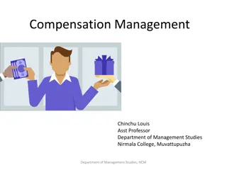
Enhancing Performance of EHV Lines through Series Compensation

Series compensation, involving connecting capacitors in series with electrical transmission lines, aims to improve EHV line performance by decreasing transmission impedance and enhancing voltage stability and transient stability. The method is a robust tool to optimize power transmission efficiency. Utilizing series capacitive compensation effectively increases the transmitted power and aids in managing power oscillations. Explore the objectives, benefits, and application of series compensation in EHV systems through this comprehensive guide.

Download Presentation

Please find below an Image/Link to download the presentation.
The content on the website is provided AS IS for your information and personal use only. It may not be sold, licensed, or shared on other websites without obtaining consent from the author. Download presentation by click this link. If you encounter any issues during the download, it is possible that the publisher has removed the file from their server.
E N D
Presentation Transcript
Series Compensation Series compensation is basically a powerful tool to improve the performance of EHV lines. It consists of capacitors connected in series with the line at suitable locations.
OBJECTIVES OF SERIES COMPENSATION The basic idea behind series capacitive compensation is to decrease the overall effective series transmission impedance from the sending end to the receiving end, i.e., X in the P : (V 2 / X) Sin relationship transmission over a single line. characterizing the power
The transmittable power rapidly increases with the degree of series compensation k . Similarly, the reactive power supplied by the series capacitor also increases sharply with k and varies with angle in a similar manner as the line reactive power.
VOLTAGE STABILITY: Series capacitive compensation can also be used to reduce the series reactive impedance to minimize the receiving-end voltage variation and the possibility of voltage collapse. Clearly, both shunt and series capacitive compensation can effectively increase the voltage stability limit. Shunt compensation does it by supplying the reactive load demand and regulating the terminal voltage. Series capacitive compensation does it.
IMPROVEMENT OF TRANSIENT STABILITY: The powerful capability of series line compensation is to control the transmitted power can be utilized much more effectively to increase the transient stability limit and to provide power oscillation damping. The equal area criterion, to investigate the capability of the ideal shunt compensator to improve the transient stability, is used again here to assess the relative increase of the transient stability margin attainable by series capacitive compensation.
POWER OSCILLATION DAMPING: Controlled series compensation can be applied effectively to damp power oscillations, for power oscillation damping it is necessary to vary the applied compensation so as to counteract the accelerating and decelerating swings of the disturbed machine(s). That is, when the rotationally oscillating generator accelerates and angle increases (d /dt > 0), the electric power transmitted must be increased to compensate for the excess mechanical input power. Conversely, when the generator decelerates and angle decreases (d /dt < 0), the electric power must be decreased to balance the insufficient mechanical input power.
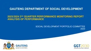
A capacitor is inserted by turning off Thyristor Valve And It is bypassed by turning on the corresponding thyristor valve.
Basic VI characteristic with is series connected components are as follows: In voltage control mode, capacitive banks are progressively by passed by the thyristor valves to reduce the overall capacitive reactance in a step like manner, as the current is increased from Iminto Imax. Thus it maintains a compensating voltage with increased line current. In Impedance compensation mode, TSSC is applied to maintain the maximum rated compensating reactance at any line current upto the rated maximum. In practice, TSSC is operated with a current limiting reactor in series.
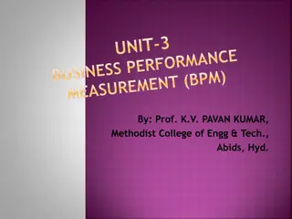
Thyristor-Controlled Series Capacitor (TCSC) It consists of the series compensating capacitor shunted by a TCR. In a practical TCSC implementation, several such basic compensators may be connected in series to obtain the desired voltage rating and operating characteristics. This arrangement is similar in structure to the TSSC and, if the impedance of the reactor, XL, is sufficiently smaller than that of the capacitor, XC, it can be operated in an on/off manner like the TSSC. Basic TCSC Scheme
The TCSC concept is that capacitor is inserted directly in series with the transmission line and the thyristor controlled inductor is mounted directly in parallel with the capacitor. Thus no interfacing equipment like high voltage transformer is required. So TCSC is more economic than some other challenging FACTS technologies.
TCSC plays vital roles in the operation and control of power systems such as 1. Enhancing power flow 2. limiting fault current 3. Enhancing transient 4. Dynamic stability Uses of TCSC Increases power transmission capability Improves system stability Reduces system losses Improves voltage profile of the lines
Operating modes of TCSC 1. Blocking mode 2. Bypass mode 3. Capacitive boost mode(Capacitive Vernier mode) 4. Inductive boost mode(Inductive vernier mode)
However, the basic idea behind the TCSC scheme is to provide a continuously variable capacitor by means of partially canceling the effective compensating capacitance by the TCR.
CHARACTERISTICS OF TCSC: Below Figure shows the characteristics of TCSC. is the delay angle measured from the crest of the capacitor voltage or equivalently, the zero crossing of the line current. Therefore, with the usual TCSC arrangement in which the impedance of the TCR reactor XLis smaller than that of the capacitor, XC, the TCSC has two operating ranges around its internal circuit resonance.
Advantages of TCSC Increase power transmission capability Improve system stability Reduce system losses Improve voltage profile of the lines Optimize power flow between parallel lines Damping of the power swings from local and inter area oscillations Application of TCSC Accurately regulating the power flow on a transmission line Damping inter area power oscillations Mitigating sub-synchronous resonance (SSR) Improving transient stability
Static Synchronous Series Compensator (SSSC) The SSSC is one of the most recent FACTS devices for power transmission series compensation. It can be considered as a synchronous voltage source as it can inject an almost sinusoidal voltage of variable and controllable amplitude and phase angle, in series with a transmission line. The injected voltage is almost in quadrature with the line current. A small part of the injected voltage that is in phase with the line current provides the losses in the inverter. Most of the injected voltage, which is in quadrature with the line current, provides the effect of inserting an inductive or capacitive reactance in series with the transmission line. The variable reactance influences the electric power flow in the transmission line.
Voltage sourced converter based series compensator is called static synchronous series compensator (SSSC) Basic Operating Principle: It can be explained with reference to conventional series capacitive compensator. SSSC can provide capacitive or inductive compensatory voltage independent of the line current upto its specified current rating in voltage control mode. In reactance control mode, SSSC is established to maintain the maximum rated capacitive or compensating reactance at any line current upto rated maximum. The basic configuration of a SSSC is shown in Fig.
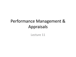
Basic two-machine system with a series capacitor compensated line and associated phasor diagram.
With synchronous voltage source replacing the series capacitor
A Static Synchronous Series Compensator operated without an external energy source as Reactive Power with output voltage is in quadrature with and fully controllable independently of the transmission line current for the purpose of increasing or decreasing the overall reactive voltage drop across the transmission line and thereby controlling the electric power flow. The SSSC FACTS device can provide either capacitive or inductive injected voltage compensation. If SSSC-AC injected voltage (Vs), lags the line current IL by 90 , a capacitive series voltage compensation is obtained in the transmission line and If leads IL by 90 , an inductive series compensation is achieved.
Theory of the SSSC Figure shows a single line diagram of a simple Transmission line with an inductive transmission reactance, XL, connecting a sending end voltage source, and a receiving end voltage source, respectively.
Where Xeff is the effective total transmission line reactance between its sending and Receiving power system ends, including the equivalent variablereactance inserted by the equivalent injected voltage (Vs) (Buck or Boost) by the SSSC-FACTS Compensator.
Transmitted Power vs. Transmission angle attainable with series capacitive compensation as a parametric function of the degree of series compensation


WITH OUT STORAGE and (b)WITH STORAGE")


 CONTROL")