Reactor Sizing and Conversion in Chemical Engineering
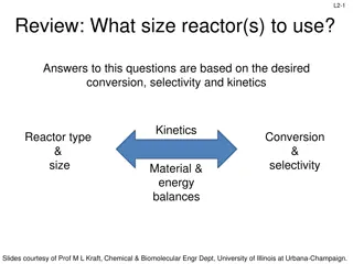
This chapter explores the sizing of Continuous Stirred Tank Reactors (CSTR) and Plug Flow Reactors (PFR) using conversion values and overall conversion. It covers the definition of conversion, batch reactor design equations, design equations for flow reactors, and more. The content delves into the mole balances, reactor volumes calculations, and design considerations for achieving specified conversions in various types of reactors.

Download Presentation

Please find below an Image/Link to download the presentation.
The content on the website is provided AS IS for your information and personal use only. It may not be sold, licensed, or shared on other websites without obtaining consent from the author. Download presentation by click this link. If you encounter any issues during the download, it is possible that the publisher has removed the file from their server.
E N D
Presentation Transcript
Chapter 2 Conversion and Reactor sizing
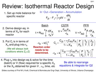
Overview In the first chapter the general mole balance was derived for different reactors In this chapter, these equations are used to size CSTR and PFR using Conversion Value and overall conversion of CSTR and PFR arranged in series
2.1 Definition of Conversion Conversion is the number of moles of reactant A (limiting reactant) that has been reacted per mole of A fed to the system of mole XA= A reacted mole of A fed For irreversible XA=1 complete conversion For reversible Xmax=Xeequilibrium conversion
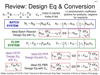
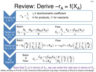
2.2 Batch Reactor Design Equation After time t, the number of moles of A remaining is = = 0 0 0 ) 1 ( 1 ( ) N N N X N X A A A A d N X dN dX = = = 0 A A r V A N 0 A dt dt dt dX = N r V A differential form 0 A dt Batch reactor design equation used for reaction rate data analysis t X X N dX dX 0 0 0 = = 0 A dt t N Integral form 0 A r V r V A A This equation gives the time required to achieve a specified conversion X The longer the reactants are left in the reactor, the greater the conversion
2.3 Design equation for flow reactor Mole balance for reactant A around the reactor In liquid phase CA0is the solution molarity (moles/volume) F = 0 F F X 0 0 A A A A consumed X = 1 ( A ) F F 0 A A = F C 0 0 0 A P y P In gas phase = = 0 0 0 A A C ideal gas law 0 A RT RT 0 0
CSTR The mole balance for CSTR yields FA0 F F = 0 A A V r A 1 ( 0 ) F F X F X ) FA = = 0 0 A A A r V ( r A A exit This equation calculates the CSTR volume necessary to achieve a specified conversion X Because of perfect mixing, the exit conc is identical to the conc inside the reactor and the reaction rate is evaluated at the exit conditions
Levenspiel CSTR Plot Volume = Area of rectangle
2.3.2 Tubular Flow Reactor (PFR) No gradient change in T, CA & -Ra The reactants are consumed as they enter and flow axially down the reactor dF = A r A dV ( A dV 1 ( )) d F X = 0 r A dX = F r Differential form of design for PFR A A r r 0 0 0 0 A A dV V X X F dX dX = = 0 A dV F 0 A Integral form used to calculate volume required to achieve specified conversion X
Levenspiel PFR Plot Volume= area under the curve
2.3.3 Packed Bed Reactor Packed bed reactors are analogous to PFR Differential form of the design equation used to analyze the reactor pressure drop dX F 0 = ' r A A dW Integral form used to determine the catalyst weight in the absence of pressure drop = = = 0 0 0 When P X W X dX 0 = W F 0 A ' r A
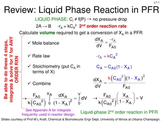
Applications of the design equations We can size the reactor from the reaction rate, as a function of conversion For the first order 1 1 1 = = 1 ( 0 A ) r kC kC X = A A 1 r kC X 0 A A For irreversible reactions of greater than zero order 1 , 1 , 0 , X r thus and V A r A For reversible reactions X X 1 , , 0 , r thus and V e A r A
2.5 Reactors in series For reactors in series where no side stream either fed or withdrawn, the conversion at point i is defined as reacted A of moles Total Xi = int up to po i Moles of A fed to the first reactor The molar flow rate at point i is given by = 0 F F F X 0 Ai A A i FA0 FA1 FA2 FA3 i=1 X1 i=2 X2 i=3 X3
2.5.1 CSTR in Series For 2 CSTR in series 1 r FA0 = V F X 1 0 1 A A ( )( r ) F F X F F X F F i=1 X1 = = 0 0 1 0 0 2 1 2 A A A A A A V FA1 2 r 2 2 A A F -rA1 = 0 ( ) A V X X 2 2 1 r 2 A i=2 X2 FA2 -rA2
Levenspiel CSTR Plot Volume of CSTR2 Volume of CSTR1 For the same overall conversion, the total volume for 2 CSTRs in series is less than that required for one CSTR
CSTR and PFR Comparison PFR can be modeled with a large number of CSTRs in series. This concept can be used in Catalyst decay in packed bed reactors Transient heat effects in PFRs V5 1 2 3 4 5 V4 V1 V3 V2 1 2 3 4 5


")