Structural Assessment and Blade Design Iteration Tool Development
A spreadsheet tool was created to assess the structural viability of a proposed blade shape, incorporating a sandwich beam model with UD sparcaps and syntactic foam core. Validation of the beam model against FEA results was conducted, highlighting the relationship between beam thickness, spar width, and chord for a 45.5m blade design.

Download Presentation

Please find below an Image/Link to download the presentation.
The content on the website is provided AS IS for your information and personal use only. It may not be sold, licensed, or shared on other websites without obtaining consent from the author. Download presentation by click this link. If you encounter any issues during the download, it is possible that the publisher has removed the file from their server.
E N D
Presentation Transcript
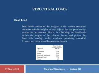
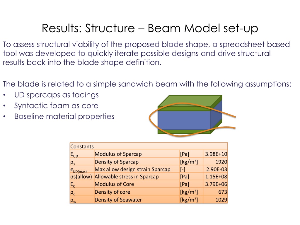
Results: Structure Beam Model set-up To assess structural viability of the proposed blade shape, a spreadsheet based tool was developed to quickly iterate possible designs and drive structural results back into the blade shape definition. The blade is related to a simple sandwich beam with the following assumptions: UD sparcaps as facings Syntactic foam as core Baseline material properties Constants EUD s UD(max) s(allow) Allowable stress in Sparcap EC Modulus of Core c Density of core w Density of Seawater Modulus of Sparcap Density of Sparcap Max allow design strain Sparcap [Pa] [kg/m3] [-] [Pa] [Pa] [kg/m3] [kg/m3] 3.98E+10 1920 2.90E-03 1.15E+08 3.79E+06 673 1029
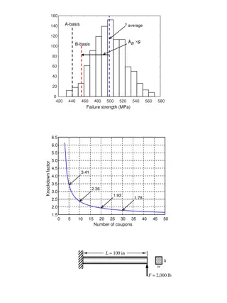
Results: Structure Beam Model Validation Additional geometric constants of the model are the relationship between the beam height to max thickness, and the sparcap width to the chord. The beam model was built to represent the latest MDEC 3-D FEA 47.5m blade. Predicted strains from the beam and FEA model were compared to get insight into the fidelity of the model and determine a realistic thickness scaling factor.
Results: Structure Beam Model Validation Notes regarding beam model validation: The beam model is able to predict the FEA model strains to an acceptable level. The FEA model has a constant thickness 10mm thick shell. This is likely to factor into the overprediction of strains by the beam model near max chord due to large shell component in this area. The FEA model has overlapping elements of the spar and the core. This is likely to underpredict the FEA strains, but is not expected to have a very large impact as the foam is soft compared to the spars. A ratio of beam thickness to max airfoil thickness of 1.00 is used to give close matching results. This tuning is expected to be dependent on the ratio of spar width to overall width, which in this case is ~28% for most of the blade.
Results: Structure 45.5m Loop 1Blade Structural Inputs for the 45.5m Loop 1 blade:
Results: Structure 45.5m Loop 1Blade Structural Inputs for the 45.5m Loop 1 blade:
Results: Structure 45.5m Loop 1Blade The ratio of beam thickness to airfoil (absolute) thickness was assumed to be 0.95. This is reduced from the ratio of 1.00 derived from the FEA validation to account for the difference in sparcap width to chord ratio. To estimate reasonable sparcap widths, a basic planform layout was created to fit a reasonably sized spar. For production efficiency, it is desirable to have a spar of constant width, or achieve a step in the spar width near the tip through a scarf transition. Due to the thick spar requirement, neither option seems plausible, so the spar is assumed to exhibit a linear taper from root to tip.
Results: Structure 45.5m Loop 1Blade The beam tool analyzes each section of the blade via the beam assumptions and calculates the required spar thickness to limit the maximum strain in the spar to the stain limit for flapwise (thrust) bending. The chart shows the beam thickness with spar thickness extending from the outer shell towards the center of the beam. Between ~7 and ~19m span, the spars would cross the neutral axis of the beam, making it impossible to build, and violating the closed form solution.
Results: Structure 45.5m Loop 1Blade To avoid interference of the spars, the blade must gain thickness. In the beam model, spar thickness is modified to allow clearance in the spars and limit the maximum thickness to 20cm. The model calculates required blade overall thickness to achieve UD strain limit with the given moment distribution.
Results: Structure 45.5m Loop 1Blade Increased thickness is translated to a modified T/C distribution which is passed back to the Hydrodynamic design for loop 2.
Results: Structure 45.5m Loop 1Blade Takeaways from Structure Loop 1 The blade must become thicker mid-span to meet structural design criteria. A modest increase in thickness to ~28% T/C at mid-span will make structure possible. Spars are very thick compared to common wind-turbine spars - 20cm vs. 5cm. Spars taper in width as they are too thick for outboard scarf joint and increased width inboard is desired and necessary. Spar offset for shell thickness/bondline has not been included in this study