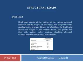
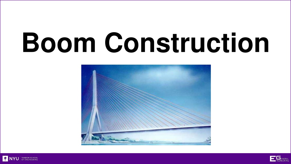
Understanding Structural Engineering: The Science Behind Boom Construction
Exploring the principles of boom construction, this content covers the objectives, types of failures, and structural considerations. From defining a boom to examining common failure modes such as corrosion and stress, this detailed guide provides insights into designing and testing structural booms for heavy objects.

Download Presentation

Please find below an Image/Link to download the presentation.
The content on the website is provided AS IS for your information and personal use only. It may not be sold, licensed, or shared on other websites without obtaining consent from the author. Download presentation by click this link. If you encounter any issues during the download, it is possible that the publisher has removed the file from their server.
E N D
Presentation Transcript
Overview Objectives Background Materials Procedure Rules of the Competition Report/Presentation Closing
Objectives What is a boom? How and why do materials fail? Stress and strain Design light-weight boom to hold significant load Understand factors engineers consider when designing a boom Construct and test boom
Boom Lifts and moves heavy objects Objects usually much heavier than the boom Examples: Construction cranes Computer monitor arms Cantilever bridges Rotating bridges
Common Structural Modes of Failure Corrosion Thermal cycling Thermal shock Breakage under load Instant fracture Delayed response (fatigue)
Corrosion Exposure to caustic chemical for extended periods Acids Salt Water (rust) Air (oxidation) Substances and material react Material weakened by being eaten away Examples: Iron rusting (exposing iron to water) Wind blowing sand on rocks, bridges, etc.
Thermal Cycling Material s temperature changes continuously over time Material cracks or shatters due to stresses created by expansion/contraction Example: Elastic in clothes cracks once removed from clothes dryer
Thermal Shock Material undergoes extreme temperature changes in a short time period Mixed temperatures throughout material cause compression and expansion, resulting in cracks Example: Hot glass bottle placed into ice cold water, bottle would explode and shatter
Breakage Under Load Maximum load supported by material is exceeded Material cracks/crumbles (i.e. thermal shock) Over usage Too many load cycles
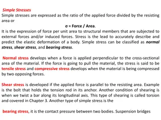
Stress and Strain Stress: measure of internal force that keeps material together Resists from change of body Strain: measure of deformation (elongation/compression) of material Change from original dimension Examples: Stretching of rope while pulling Car tire under load
Stress-Strain Figure Fixed Support Stress ( ) = ? Cross-sectional area of bar ? Lo Strain ( ) = ?? ?0 DL Load F F = applied force DL = change in length A = cross-sectional area Lo = original length
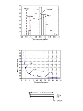
Stress-Strain Graph UTS Key points/regions UTS (Ultimate Tensile Strength) {P} Fracture Stress {E} Stress ( ) [Pa] Elastic Region {E} Plastic Region {P} Fracture Stress Strain ( ) [mm/mm]
Stress-Strain Graph UTS UTS - greatest amount of stress material will {P} withstand without failing {E} Stress ( ) [Pa] Plastic instability occurs when past UTS UTS = ???? Fracture Stress ?0 Pmax = applied force Ao = cross-sectional area Strain ( ) [mm/mm]
Stress-Strain Graph UTS Fracture Stress - stress at which the material {P} completely fails {E} Stress ( ) [Pa] ?? ?0 Fracture Stress = Pf = applied force Ao= cross-sectional area Fracture Stress Strain ( ) [mm/mm]
Stress-Strain Graph Strain will disappear when UTS stress is removed {P} Stress and strain vary linearly, obeying Hooke s Law ( ) {E} Stress ( ) [Pa] Stiffness of material found by Young s Modulus of Elasticity: Fracture Stress E = / (slope of elastic region) Strain ( ) [mm/mm]
Stress-Strain Graph Strain will NOT disappear when stress is removed UTS {P} Permanent deformation Range of plasticity: {E} Stress ( ) [Pa] Ductile materials deform considerably before fracture Fracture Stress Brittle materials do not deform much and failure occurs suddenly Strain ( ) [mm/mm]
Stress-Strain Example The Plastic Pen Cap and Nervous Student 1. Elastic Region - Student applies force, bending tip of pen cap 1 back. When force is removed, tip of cap returns to original position. 2 2. Plastic Region - Student twists and bends tip of cap. When force is removed, the tip of cap stays mangled. 3. UTS - Student bends cap some more. Cap still in one piece, but 3 certain areas are very weak and on the verge of breaking. 4. Fracture Stress - Student bends cap one more time. The cap 4 finally breaks into two pieces.
Materials for Lab 2 thin dowels (0.8 cm dia. x 122 cm) 2 thick dowels (1.1 cm dia. x 122 cm) 6 x 30.5 cm bamboo skewers 3D-printed dowel connectors Cellophane tape Kevlar string
Competition Ratio Unadjusted Ratio: Adjusted Ratio:
Competition Rules Design Specifications TA initials and dates sketches of design before Design materials are distributed Specifications Materials may be cut and arranged in any way Boom must extend a horizontal distance of at least Disqualifications 1.5 m after mounting Construction must be completed in time allotted Declaration of No more than 2 minutes to anchor boom winners Weight will be added until boom deflects 0.2 m
Competition Rules Disqualifications Design Design is less than 1.5 m horizontally when Specifications mounted Disqualifications Exceeds 2 minute max time for anchoring boom Boom must only touch anchor Declaration of (10.2 cm dia. pipe) winners
Competition Rules Declaration of Winners Design Design with highest adjusted ratio wins competition Specifications Decision of TAs are FINAL Disqualifications Declaration of winners
Competition Boom Design Observe provided materials Boom Design Brainstorm design strategy with team members Test Note design decisions and necessary design changes Sketch proposed design Post-Test Have TA initial sketch and notes Build boom according to sketch
Competition Test TA will create a spreadsheet to record competition results Boom Design Weigh boom and announce value to TA When instructed, fasten boom to anchor Test Announce when DONE! , to record time TA measures length from tip of anchor to weight mounting point on Post-Test boom Must meet 1.5 m requirement Add weights until boom deflects 0.2 m vertically, or fails
Competition Post-Test TA announces winner of competition Boom Design Team with largest adjusted ratio wins Test Copies of spreadsheet available to all teams on eg.poly.edu Post-Test TA initials and scans original data
Assignment: Report Optional BONUS Individual lab report Title page Discussion topics in the manual Include class results and photo of boom
Assignment: Presentation Team presentation State rules of competition Describe your design and its concepts Include table of class results, sketches, photo of boom How could your current design be improved?
Closing Think safety! Be careful not to poke classmates with the dowels Have all original data signed by TA Submit all work electronically Clean up workstations Return all unused materials to TA
Boom Construction Competition QUESTIONS?