Understanding Resistive Circuits in Electrical Circuit Theory Class

Explore the concepts of resistive circuits in ECEN 214 class with Prof. Adam Birchfield at Texas A&M University. Learn about series and parallel connections of resistors, solving examples, understanding Kirchoff's laws, and determining equivalent resistances. Enhance your knowledge of electrical circuit theory through practical applications and theoretical explanations.

Download Presentation

Please find below an Image/Link to download the presentation.
The content on the website is provided AS IS for your information and personal use only. It may not be sold, licensed, or shared on other websites without obtaining consent from the author. Download presentation by click this link. If you encounter any issues during the download, it is possible that the publisher has removed the file from their server.
E N D
Presentation Transcript
ECEN 214, Spring 2022 Electrical Circuit Theory Class 3: Resistive Circuits Prof. Adam Birchfield Dept. of Electrical and Computer Engineering Texas A&M University abirchfield@tamu.edu
2 Review: Parallel or Series? E D Elements in series share one junction, with nothing else connected to the same junction, and they have the same current (KCL) Elements in parallel share two junctions, regardless of what else is connected, and they have the same voltage (KVL) Which resistors in these circuits are in series and parallel? A + _ G F B H + _ + _ I J C
3 Example with Resistors in Series Solve for ?? and the voltage across each resistor _ _ + + ?1 11 5 + + _ 8 100 ? _ _ _ + + ?5 13 13
4 Resistors in Series _ _ Consider a circuit with two or more resistors connected in series. The current through each resistor must be the same. The current through each resistor must be the same. By virtue of Ohm s law, we then get: ?1= ???1 ?2= ???2 ??= ????. + + + + _ _ _ _ + + ?? ?? Using Kirchoff s Voltage Law (KVL) around the loop: ??= ?1+ ?2+ + ?? = ???1+ ???2+ +???? = ???1+ ?2+ + ?? = ????? ???=?1+ ?2+ + ??
5 Resistors in Series _ _ + + + + _ + _ _ _?? _ + + ?? For the purposes of finding the current flowing through the circuit, the series connection of the multiple resistors can be replaced by a single equivalent resistor whose resistance is the sum. ???= ?1+ ?2+ + ??
6 Example with Resistors in Parallel Solve for ?? and the current through each resistor ?1 ?3 ?2 + _ 20 5 7 90 ?
7 Resistors in Parallel Consider a circuit with two or more resistors connected in parallel. Now the current in each branch is different but the voltage across each resistor is the same. ??= ?1?1= ?2?2= = ???? ?1 ?2 ?? . . . + _ ?1 ?2 ?? By virtue of Ohm s law, we then get: Using Kirchoff s Current Law (KCL): ??= ?1+ ?2+ + ?? =?? +?? ?? ?? 1 1 ?1+ 1 ?2+ + 1 + + ?? ???= or equivalently ?1 ?2 1 ?1 1 ?2 1 = ?? + + + 1 ?? ???= 1 ?1+1 ?2+ +1 ?? ??? ?? =
8 Equivalent Resistances Resistors in Parallel ?1 ?2 ?? + _ . . . + _ ?1 ?2 ?? For the purposes of finding the current flowing through the source, the parallel connection of resistors can be replaced with a single equivalent resistor such that: 1 1 ?1 +1 1 1 = + + ???= ??? ?2 ?? 1 ?1+1 ?2+ +1 ??
9 Equivalent Resistances Most often, we use these concepts with just two resistors at a time. In that case, the formulas simplify to: Parallel combination Series combination Req= R1+ R2 R1R2 R1+ R2 Req= Note that: Series equivalent resistances are always larger than each individual component, and Parallel equivalent resistances are always smaller than each individual component,
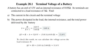
10 Example For the circuit shown: (a) Find the voltage ?, (b) Find the power delivered to the circuit by the current source, (c) Find the power dissipated in the 10 resistor.
11 Voltage Dividers If a voltage is applied across a series resistance combination, the voltage is divided (unequally) across the resistors. ?? ??= ?1+ ?2= ??1+ ??2 ? = + ?1+?2 ? ?1 _ ?1 ?1= ??1 ?2= ??2 + _ ?? ?1 ?2 + = ?? = ?? ?1+ ?2 ?1+ ?2 ?2 _ ?2 These ratios are known as voltage dividers The voltage is split proportionally according to the resistance values. Higher voltage goes to the larger resistor. Note: This kind of configuration occurs so frequently that it is worthwhile committing this result to memory.
12 Example of Voltage Dividers For the voltage divider circuit shown: If ?1= 1? and ?2= 2? , determine the voltages ?1 and ?2. Also determine the power generated by the source. Suppose we want ?2= 9? and that the source is capable of producing no more than 250mW of power. What are the smallest resistors that can be used to achieve these specifications? + ?1 - ?1 + + _ ?2 _ ?2 12?
13 Current Dividers If a current is applied to a parallel resistance combination, the current is divided (unequally) through the resistors. ?1?2 ?1+?2 ?1?1= ?2?2= ?????= ?? ?2 ?1 ?1 ?2 ?? ?2 ?1 ?1= ?? ?2= ?? ?1+ ?2 ?1+ ?2 These ratios are known as current dividers The current is split proportionally according to the resistance values. Higher current goes to the smaller resistor. Again, commit this result to memory. Beware: The current dividers are the opposite of the voltage dividers. This will be a source of great confusion to some.
14 Example of Current Dividers Find the current ? in the circuit shown. 2? ? 24?? 4? 4? 4?
15 Voltage and Current Dividers The concepts of voltage and current division can be applied to more than two resistors. + _ + _ + ?? . . . + _ ?? ??= ?? ?? _ ?1+ ?2+ + ?? _ _ ?? + + ?? 1 ?? ?? 1 ??? ?? ??= ?? ?2 ?? ?1 1 . . . ?1 ?2 ?? ?? ?? = ?? 1 ?1+1 ?2+ +1 ??
16 -Y ( -T) Equivalent Circuits Sometimes we encounter a triangular configuration of resistors. These cannot be simplified by series or parallel equivalents. ?? ?? a b a b ?? ?? ?? ?? c c Delta ( ) configuration Pi ( ) configuration
17 -Y ( -T) Equivalent Circuits configurations can be transformed to a Y (or T) configuration. Sometimes by doing so, the resulting circuit can be further simplified. b a a b ?1 ?2 ?2 ?1 ?3 ?3 c c Y configuration T configuration
18 -Y ( -T) Equivalent Circuits For the and Y configurations to be equivalent, the resistances between each pair of nodes must be equivalent. b a b a ?? ?1 ?2 ?? ?? ?3 c c -configuration Y- configuration ?? ??+ ?? ??+ ??+ ?? ?? ??+ ?? ??+ ??+ ?? ?? ??+ ?? ??+ ??+ ?? ??? ?1+ ?2 ??? ?1+ ?3 ??? ?2+ ?3
19 -Y ( -T) Equivalent Circuits With some straightforward algebra, we can solve for ??, ??, and ?? in terms of ?1, ?2, and ?3 or vice-versa. The following relationships result. ?? ?? ??+ ??+ ?? ??=?1?2+ ?2?3+ ?1?3 ?1= ?1 ?? ?? ??+ ??+ ?? ??=?1?2+ ?2?3+ ?1?3 ?2= ?2 ??=?1?2+ ?2?3+ ?1?3 ?? ?? ??+ ??+ ?? ?3= ?3 These 3 equations allow us to replace a structure with an equivalent Y structure. These 3 equations allow us to replace a Y structure with an equivalent structure. See if you can derive these equations on your own then put them on your note sheet for the exam!
20 Example of delta-wye transformation Find the voltage ? in the circuit shown. ?? ?? ??+ ??+ ?? ?? ?? ??+ ??+ ?? ?? ?? ??+ ??+ ?? ??=?1?2+ ?2?3+ ?1?3 ?1= ?1 ??=?1?2+ ?2?3+ ?1?3 ?2= ?2 ??=?1?2+ ?2?3+ ?1?3 ?3= ?3
21 A Word on Making Measurements Measure voltage with a voltmeter: probes across the two nodes you want to measure Measure current with an ammeter: break the circuit and place meter in series so that you can measure the current through it Measuring voltage: one way is to use a Wheatstone bridge. The resistance of the potentiometer is varied until the ammeter shows no current flowing between nodes a and b. Therefore, the voltage ???= 0, and ?1= ?3, ?2= ??. Hence you can substitute and find ??= ?3 ?1 ?2
22 Wheatstone Bridge Example Say ?1= 1 , ?2= 2 . You put an unknown resistor ?? as shown, and then you adjust ?3 until the Ammeter shows 0 A. This occurs with ?3= 4.3 . What s the unknown resistance?
23 Assignments Get the Zybook and complete sections 2.4, 2.6, 2.7, 2.8, 3.2, 3.3, 3.5 Due 4pm on Monday, Jan 31 If you haven t done the earlier sections that were due today, do these as well See the syllabus for details on how to get the Zybook Homework #1 on Canvas Also due 4pm on Monday, Jan 31 Take it as many times as needed, your best score will count. It is different each time, so it is good for additional practice. Review in-class examples and notes Practice, practice, practice! Quiz #3 on Monday