Understanding Instrument Transformers in Electrical Systems
In electrical power systems, instrument transformers play a crucial role by stepping down high currents and voltages to levels suitable for measurement using instruments like current transformers (C.T.) and potential transformers (P.T.). These transformers offer numerous advantages such as independence from circuit constants, standardization around ratings, isolation from power circuits, low power consumption, and the ability to operate multiple instruments from a single transformer. Key terms related to instrument transformers include Transformation Ratio (R) and Nominal Ratio (Kn) for both current and potential transformers.

Download Presentation

Please find below an Image/Link to download the presentation.
The content on the website is provided AS IS for your information and personal use only. It may not be sold, licensed, or shared on other websites without obtaining consent from the author. Download presentation by click this link. If you encounter any issues during the download, it is possible that the publisher has removed the file from their server.
E N D
Presentation Transcript
INSTRUMENT TRANSFORMER
Introduction Introduction In electrical power system the range of current and voltage is very high and so it is not possible to measure these values directly by any meter of reasonable size and construction. So there is a need to step down these voltages or currents to such a value so that it can be easily measured. Such transformers which are used with the measuring instruments are called instrument transformers.
Introduction Introduction Transformer used for the measurement of current is called the current transformer or C.T. Transformer used for measurement of voltage is called potential transformer or P.T.
Advantages of Instrument Transformer Advantages of Instrument Transformer Their readings do not depend upon circuit constants such as R, L and C. It is possible to standardize the instrument around their ratings. The measuring circuit is isolated from the power circuit There is low power consumption in the metering circuit Several instruments can be operated from a single instrument transformer.
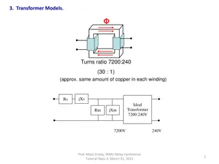
Terms Related to Instrument Transformer Terms Related to Instrument Transformer Transformation ratio (R): For a current transformer or C.T., it is defined as the ratio of primary winding current to secondary winding current. That is,
Terms Related to Instrument Transformer Terms Related to Instrument Transformer Transformation ratio (R): For a potential transformer or P.T., it is defined as the ratio of primary winding voltage to secondary winding voltage. That is,
Terms Related to Instrument Transformer Terms Related to Instrument Transformer Nominal Ratio (Kn): For a current transformer or C.T., it is defined as the ratio of rated primary winding current to rated secondary winding current. That is,
Terms Related to Instrument Transformer Terms Related to Instrument Transformer Nominal Ratio (Kn): For a potential transformer or P.T., it is defined as the ratio of rated primary winding voltage to rated secondary winding voltage. That is,
Terms Related to Instrument Transformer Terms Related to Instrument Transformer Turns Ratio (n): For a current transformer or C.T., it is defined as the ratio of number of secondary winding turns to number of primary winding turns. That is,
Terms Related to Instrument Transformer Terms Related to Instrument Transformer Turns Ratio (n): For a potential transformer or P.T., it is defined as the ratio of number of primary winding turns to number of secondary winding turns. That is,
Instrument Transformer Instrument Transformer Burden of an Instrument Transformer The secondary load of a C.T. is generally called the burden to distinguish it from the load of the current whose current is being measured. The burden in a C.T. metering circuit is the impedance presented to its secondary winding.
Instrument Transformer Instrument Transformer Burden of an Instrument Transformer The typical burden ratings for IEC C.T.s are, 1.5 VA, 3 VA, 5 VA, 10 VA, 15 VA, 20 VA, 30 VA, 45 VA, 60 VA. For ANSI/IEEE burden ratings are B-0.1, B-0.2, B-0.5, B-1.0, B-2.0 and B- 4.0. This means a C.T. with a aburden rating of B-0.2 can tolerate upto 0.2 of impedance in the metering circuit before its secondary accuracy falls outside the accuracy specification.
Instrument Transformer Instrument Transformer Current Transformer Potential Transformer
Instrument Transformer Instrument Transformer Classification of Current Transformers Bar Type: They are usually bolted to the current caring device and is insulated for the operating voltage of the system. They have a permanent bar installed as a primary conductor.
Instrument Transformer Instrument Transformer Classification of Current Transformers Wound C.T.: Wound C.T. has a primary and secondary winding like a normal transformer. They are designed to measure currents from 1 amp to 100 amps. Wound primary C.T. are available in ratios from 2.5:5 to 100:5. The wound type provides excellent performance under a wide operating range.
Instrument Transformer Instrument Transformer Classification of Current Transformers Window: They don t have any primary winding and so is installed around the primary conductor. The electric field created by current flowing through the primary conductor interacts with the C.T. core to transform the current to the appropriate secondary output. Window C.T. are the most commonly used.
Instrument Transformer Instrument Transformer Classification of Current Transformers Split Core C.T.: Split core C.T. have one end removable so that the load conductor or bus bar does not have to be disconnected to install the C.T.. There are used for measuring currents
Instrument Transformer Instrument Transformer Classification of Potential Transformers Transformer: to hese Electromagnetic Transformers Transformers where both the winding, Primary and Secondary are wound to the magnetic core. These Transformers are usually used in relay, meter and high voltage circuits. In this type of Transformer, the Primary Winding is connected to the Phase and Secondary Winding is in contact with the ground. Potential similarities have the Primary
Instrument Transformer Instrument Transformer Classification of Potential Transformers Capacitive Potential Transformer: These Transformers are also known as Coupling type or Potential Dividers or the Bushing types. The Capacitors are wound to either the Primary or Secondary Winding with the voltage measured across the Secondary Winding. This Transformer is expensive and used for the Power line carrier communication.
Instrument Transformer Instrument Transformer Difference Between C.T. and P.T. CURRENT TRANSFORMER POTENTIAL TRANSFORMER Secondary must be kept under short circuit Secondary is open circuited. condition always. Windings carry full line current. Primary current is independent of secondary. It can be considered as series transformer under Windings have full line voltage. Primary is dependent on secondary. It can be considered as parallel transformer under short circuit condition. Small voltage exists across its terminals. open circuit condition. Full line voltage appears across its terminals.
CURRENT TRANSFORMER CURRENT TRANSFORMER The primary winding of a C.T. is connected in series with the line whose current needs to be measured. The primary winding has less number of turns and so the voltage drop across it is also less. The secondary winding on the other hand has large number of turns. The meters (ammeter or the current coil of the wattmeter) are connected directly across the secondary winding.
CURRENT TRANSFORMER CURRENT TRANSFORMER Thus we can say that the secondary side of the C.T. is operated nearly under short circuit condition. Since the secondary is nearly short circuited one of the terminals of the secondary winding is earthed to protect the equipment and also the personnel in the case of an insulation breakdown in C.T.
CURRENT TRANSFORMER CURRENT TRANSFORMER
CURRENT TRANSFORMER CURRENT TRANSFORMER
CURRENT TRANSFORMER CURRENT TRANSFORMER R1 is the resistance of the primary winding. X1 is the reactance of the primary winding. R2 is the resistance of the secondary winding. X2 is the reactance of the secondary winding. N1 is the number of turns of primary. N2 is the number of turns of secondary I1 is the primary current. I2 is the secondary current.
CURRENT TRANSFORMER CURRENT TRANSFORMER RL is the resistance of the burden. XL is the reactance of the burden. E1 is the primary induced emf. E2 is the primary induced emf. I0 is the excitation current. Im is the magnetization component of excitation current. Iw is the loss component of excitation current.
CURRENT TRANSFORMER CURRENT TRANSFORMER is the angle between I0 and flux . is the phase angle of the transformer. angle between the secondary current and the secondary induced emf.
CURRENT TRANSFORMER CURRENT TRANSFORMER
CURRENT TRANSFORMER CURRENT TRANSFORMER