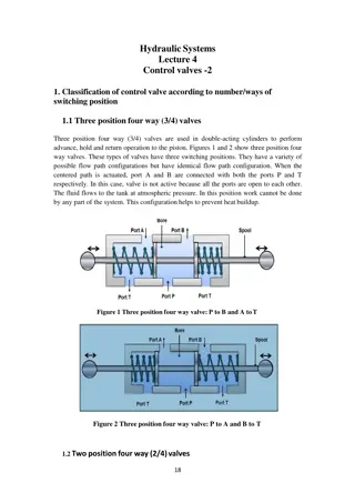
Caterpillar Cat 305CR Mini Hydraulic Excavator (Prefix DSA) Service Repair Manual Instant Download
Please open the website below to get the complete manualnn// n

Download Presentation

Please find below an Image/Link to download the presentation.
The content on the website is provided AS IS for your information and personal use only. It may not be sold, licensed, or shared on other websites without obtaining consent from the author. Download presentation by click this link. If you encounter any issues during the download, it is possible that the publisher has removed the file from their server.
E N D
Presentation Transcript
Service Repair Manual Models 305CR M ini Hydraulic Excavator
305CR Mini Hydraulic Excavator DSA00001-UP (MACHINE) POWERED BY K4N ... 1/3 Shutdown SIS Previous Screen Product: MINI HYD EXCAVATOR Model: 305 MINI HYD EXCAVATOR DSA Configuration: 305CR Mini Hydraulic Excavator DSA00001-UP (MACHINE) POWERED BY K4N Engine Disassembly and Assembly 305 Mini Hydraulic Excavator Machine Systems Media Number -RENR5546-04 Publication Date -01/08/2007 Date Updated -07/08/2007 i01671197 Travel Motor - Remove SMCS - 4351-011 Removal Procedure Start By: A. Release the hydraulic system pressure. Refer to Disassembly and Assembly, "Hydraulic System Pressure - Release". B. Remove the track. Refer to Disassembly and Assembly, "Track - Remove and Install". C. Remove the final drive sprocket. Refer to Disassembly and Assembly, "Final Drive Sprocket - Remove and Install". Personal injury can result from hydraulic oil pressure and hot oil. Hydraulic oil pressure can remain in the hydraulic system after the engine has been stopped. Serious injury can be caused if this pressure is not released before any service is done on the hydraulic system. Make sure all of the attachments have been lowered, oil is cool before removing any components or lines. Remove the oil filler cap only when the engine is stopped, and the filler cap is cool enough to touch with your bare hand. NOTICE Care must be taken to ensure that fluids are contained during performance of inspection, maintenance, testing, adjusting and repair https://127.0.0.1/sisweb/sisweb/techdoc/techdoc_print_page.jsp?returnurl=/sis... 2020/2/14
305CR Mini Hydraulic Excavator DSA00001-UP (MACHINE) POWERED BY K4N ... 2/3 of the product. Be prepared to collect the fluid with suitable containers before opening any compartment or disassembling any component containing fluids. Refer to Special Publication, NENG2500, "Caterpillar Tools and Shop Products Guide" for tools and supplies suitable to collect and contain fluids on Caterpillar products. Dispose of all fluids according to local regulations and mandates. Note: Put identification marks on all lines and on all hoses for installation purposes. Plug all lines and all hoses. This helps to prevent fluid loss and this helps to keep contaminants from entering the system. Illustration 1 g00723963 1. Remove bolts (1) and washers. 2. Remove cover (2) . Illustration 2 g00726946 https://127.0.0.1/sisweb/sisweb/techdoc/techdoc_print_page.jsp?returnurl=/sis... 2020/2/14
https://www.ebooklibonline.com Hello dear friend! Thank you very much for reading. Enter the link into your browser. The full manual is available for immediate download. https://www.ebooklibonline.com
305CR Mini Hydraulic Excavator DSA00001-UP (MACHINE) POWERED BY K4N ... 3/3 3. Disconnect hose assemblies (3), (4), (5), and (6) from the travel motor. Illustration 3 g00726947 4. Use a suitable lifting device to support the travel motor. 5. Remove bolts (7) and washers from the travel motor. Illustration 4 g00726948 6. Remove travel motor (8) from the undercarriage frame with a suitable lifting device. Weight of the travel is 60 kg (132 lb). 7. Repeat Steps 1 through 6 for the other side of the travel motor. Copyright 1993 - 2020 Caterpillar Inc. Fri Feb 14 17:40:48 UTC+0800 2020 All Rights Reserved. Private Network For SIS Licensees. https://127.0.0.1/sisweb/sisweb/techdoc/techdoc_print_page.jsp?returnurl=/sis... 2020/2/14
305CR Mini Hydraulic Excavator DSA00001-UP (MACHINE) POWERED BY K4N ... 1/12 Shutdown SIS Previous Screen Product: MINI HYD EXCAVATOR Model: 305 MINI HYD EXCAVATOR DSA Configuration: 305CR Mini Hydraulic Excavator DSA00001-UP (MACHINE) POWERED BY K4N Engine Disassembly and Assembly 305 Mini Hydraulic Excavator Machine Systems Media Number -RENR5546-04 Publication Date -01/08/2007 Date Updated -07/08/2007 i01669600 Travel Motor - Disassemble SMCS - 4351-015 Disassembly Procedure Table 1 Required Tools Tool Part Number Part Description Qty A 1P-1862 Snap Ring Pliers 1 B 1U-7588 Pry Bar 2 Start By: A. Remove the piston motor (travel). Refer to Disassembly and Assembly, "Piston Motor (Travel) - Remove" in this manual. NOTICE Care must be taken to ensure that fluids are contained during performance of inspection, maintenance, testing, adjusting and repair of the product. Be prepared to collect the fluid with suitable containers before opening any compartment or disassembling any component containing fluids. Refer to Special Publication, NENG2500, "Caterpillar Tools and Shop Products Guide" for tools and supplies suitable to collect and contain fluids on Caterpillar products. Dispose of all fluids according to local regulations and mandates. https://127.0.0.1/sisweb/sisweb/techdoc/techdoc_print_page.jsp?returnurl=/sis... 2020/2/14
305CR Mini Hydraulic Excavator DSA00001-UP (MACHINE) POWERED BY K4N ... 2/12 Note: Put identification marks on the travel motor and on all lines for installation purposes. Plug all lines. This will help to prevent fluid loss and this helps to keep contaminants from entering the system. Note: Cleanliness is an important factor. Before the disassembly procedure, the exterior of the component should be thoroughly cleaned. This will help to prevent dirt from entering the internal mechanism. 1. Put an alignment mark across the section of the travel motor and the final drive for assembly purposes. The parts must be reinstalled in the original locations of the parts. Illustration 1 g00763560 2. Remove plugs (1). Drain the oil. Illustration 2 g00763551 3. Remove bolts (2). Remove plate (3) . https://127.0.0.1/sisweb/sisweb/techdoc/techdoc_print_page.jsp?returnurl=/sis... 2020/2/14
305CR Mini Hydraulic Excavator DSA00001-UP (MACHINE) POWERED BY K4N ... 3/12 Illustration 3 g00763571 4. Remove port plate (4) . Illustration 4 g00763578 5. Remove barrel assembly (5) . Illustration 5 g00763935 https://127.0.0.1/sisweb/sisweb/techdoc/techdoc_print_page.jsp?returnurl=/sis... 2020/2/14
305CR Mini Hydraulic Excavator DSA00001-UP (MACHINE) POWERED BY K4N ... 4/12 6. Put identification marks on piston assemblies (6) in order to indicate the locations of the pistons in the retainer plate (7) and the barrel (8). Remove piston assemblies (6) and retainer plate (7) from barrel (8) as a unit. Separate the piston assemblies from the retainer plate. Illustration 6 g00763958 7. Remove guide (9) and pins (10) from barrel (8) . Illustration 7 g00763585 8. Remove swashplate (11) . https://127.0.0.1/sisweb/sisweb/techdoc/techdoc_print_page.jsp?returnurl=/sis... 2020/2/14
305CR Mini Hydraulic Excavator DSA00001-UP (MACHINE) POWERED BY K4N ... 5/12 Illustration 8 g00763590 9. Remove piston (12), and spring (13) . Illustration 9 g00763910 10. Use a 0.25 mm (0.010 inch) feeler gauge to a 0.38 mm (0.015 inch) feeler gauge. Remove ring (14) from the groove between cover (15) and the final drive housing. Illustration 10 g00763597 https://127.0.0.1/sisweb/sisweb/techdoc/techdoc_print_page.jsp?returnurl=/sis... 2020/2/14
305CR Mini Hydraulic Excavator DSA00001-UP (MACHINE) POWERED BY K4N ... 6/12 11. Remove cover (16) . Illustration 11 g00763603 12. Remove O-ring seal (17) . Illustration 12 g00763605 13. Use Tooling (A) in order to remove retaining rings (18) . https://127.0.0.1/sisweb/sisweb/techdoc/techdoc_print_page.jsp?returnurl=/sis... 2020/2/14
305CR Mini Hydraulic Excavator DSA00001-UP (MACHINE) POWERED BY K4N ... 7/12 Illustration 13 g00763613 14. Remove gears (19). Remove gear (20) . Illustration 14 g00763623 15. Remove shaft (21). Remove bearing (22) . Illustration 15 g00763684 16. Remove pivots (23), and lip seal (24) . https://127.0.0.1/sisweb/sisweb/techdoc/techdoc_print_page.jsp?returnurl=/sis... 2020/2/14
305CR Mini Hydraulic Excavator DSA00001-UP (MACHINE) POWERED BY K4N ... 8/12 Illustration 16 g00764056 NOTICE The thread lock compound that is used on the reamer bolts may cause the reamer bolts to seize during removal. The reamer bolts should be slowly removed by hand. Do not use an impact wrench in order to remove the reamer bolts. If the reamer bolts will no longer turn during removal, do not force or complete the removal. Instead, tighten the bolts, then try to loosen them again. 17. Carefully remove bolts (25). Remove retaining rings (26) . Illustration 17 g00763700 18. Use Tooling (B) in order to separate spindle (27) from housing (28) . https://127.0.0.1/sisweb/sisweb/techdoc/techdoc_print_page.jsp?returnurl=/sis... 2020/2/14
305CR Mini Hydraulic Excavator DSA00001-UP (MACHINE) POWERED BY K4N ... 9/12 Illustration 18 g00764796 19. Remove flange (29), and bearing (30) . Illustration 19 g00764176 20. Remove gear (31) . Illustration 20 g00764194 21. Remove shaft assemblies (32), and gear (33) . https://127.0.0.1/sisweb/sisweb/techdoc/techdoc_print_page.jsp?returnurl=/sis... 2020/2/14
305CR Mini Hydraulic Excavator DSA00001-UP (MACHINE) POWERED BY K4... 10/12 Illustration 21 g00764198 22. Remove bearing cone (35), and bearing cone (38) from shaft (34). Remove bearing (36), and bearing (37) from shaft (34) . Illustration 22 g00862751 23. Remove Duo-Cone seal kit (39). Remove pins (40). Remove bearing (41) . https://127.0.0.1/sisweb/sisweb/techdoc/techdoc_print_page.jsp?returnurl=/sis... 2020/2/14
305CR Mini Hydraulic Excavator DSA00001-UP (MACHINE) POWERED BY K4... 11/12 Illustration 23 g00764855 24. If necessary, remove valve (42). Remove bearing (43) . Illustration 24 g00764867 25. Remove plugs (44), and the O-ring seals. Remove springs (45), stoppers (46), and spool (47) . Illustration 25 g00764880 26. Remove plugs (48), and the O-ring seals. Remove springs (49), and stoppers (50) . https://127.0.0.1/sisweb/sisweb/techdoc/techdoc_print_page.jsp?returnurl=/sis... 2020/2/14
305CR Mini Hydraulic Excavator DSA00001-UP (MACHINE) POWERED BY K4... 12/12 Illustration 26 g00764899 27. If necessary, remove plugs (51). Remove plug (52), and the O-ring seal. Remove plug (53) . Copyright 1993 - 2020 Caterpillar Inc. Fri Feb 14 17:41:44 UTC+0800 2020 All Rights Reserved. Private Network For SIS Licensees. https://127.0.0.1/sisweb/sisweb/techdoc/techdoc_print_page.jsp?returnurl=/sis... 2020/2/14
305CR Mini Hydraulic Excavator DSA00001-UP (MACHINE) POWERED BY K4N ... 1/12 Shutdown SIS Previous Screen Product: MINI HYD EXCAVATOR Model: 305 MINI HYD EXCAVATOR DSA Configuration: 305CR Mini Hydraulic Excavator DSA00001-UP (MACHINE) POWERED BY K4N Engine Disassembly and Assembly 305 Mini Hydraulic Excavator Machine Systems Media Number -RENR5546-04 Publication Date -01/08/2007 Date Updated -07/08/2007 i02404421 Travel Motor - Assemble SMCS - 4351-016 Assembly Procedure Table 1 Required Tools Tool Part Number Part Description Qty A 1P-1862 Snap Ring Pliers 1 B 1U-7588 Pry Bar 2 C 1U-6439 Duo-Cone Seal Installer 1 D 5P-3931 Anti-Seize Compound 1 E 9S-3263 Thread Lock Compound 1 Note: Replace all O-ring seals and gaskets. Apply a light film of"10W" oil to all components before assembly. Note: Cleanliness is an important factor. Before assembly, all parts should be thoroughly cleaned in cleaning fluid. Allow the parts to air dry. Wiping cloths or rags should not be used to dry parts. Lint may be deposited on the parts which may cause later trouble. Inspect all parts. If any parts are worn or damaged, use new parts for replacement. https://127.0.0.1/sisweb/sisweb/techdoc/techdoc_print_page.jsp?returnurl=/sis... 2020/2/14
305CR Mini Hydraulic Excavator DSA00001-UP (MACHINE) POWERED BY K4N ... 2/12 Illustration 1 g00764899 1. If necessary, install plugs (51) . Tighten the plugs to a torque of 12.3 2.45 N m (109 22 lb in). Install plug (52) , and the O-ring seal. Install plug (53) . Illustration 2 g00764880 2. Install stoppers (50) , and springs (49) . Install plugs (48) , and the O-ring seals. Tighten plugs to a torque of 79 10 N m (58 7 lb ft). Illustration 3 g00764867 https://127.0.0.1/sisweb/sisweb/techdoc/techdoc_print_page.jsp?returnurl=/sis... 2020/2/14
305CR Mini Hydraulic Excavator DSA00001-UP (MACHINE) POWERED BY K4N ... 3/12 3. Install spool (47) . Install stoppers (46) , and springs (45) . Install plugs (44) , and the O-ring seals. Tighten the plugs to a torque of 195 15 N m (144 11 lb ft). Illustration 4 g00764855 4. If necessary, install valve (42) . Install bearing (43) . Illustration 5 g00764227 5. Install bearing (41) . Install pins (40) . https://127.0.0.1/sisweb/sisweb/techdoc/techdoc_print_page.jsp?returnurl=/sis... 2020/2/14
305CR Mini Hydraulic Excavator DSA00001-UP (MACHINE) POWERED BY K4N ... 4/12 Illustration 6 g00862921 6. Use Tooling (C) in order to install Duo-Cone seal kit (39) . Illustration 7 g00764198 7. Install bearing (36) , and bearing (37) on shaft (34) . Install bearing cone (35) , and bearing cone (38) on shaft (34) . Illustration 8 g00764194 https://127.0.0.1/sisweb/sisweb/techdoc/techdoc_print_page.jsp?returnurl=/sis... 2020/2/14
305CR Mini Hydraulic Excavator DSA00001-UP (MACHINE) POWERED BY K4N ... 5/12 8. Install gear (33) , and shaft assemblies (32) . Illustration 9 g00764176 9. Install gear (31) . Illustration 10 g00764796 NOTICE During installation of the flange plate, keep the flange plate level and true. If the flange plate is not kept level and true, galling of the flange plate will result. 10. Install bearing (30) , and flange (29) . https://127.0.0.1/sisweb/sisweb/techdoc/techdoc_print_page.jsp?returnurl=/sis... 2020/2/14
Suggest: If the above button click is invalid. Please download this document first, and then click the above link to download the complete manual. Thank you so much for reading
305CR Mini Hydraulic Excavator DSA00001-UP (MACHINE) POWERED BY K4N ... 6/12 Illustration 11 g00765016 11. Install spindle (27) into housing (28) . Illustration 12 g00764056 12. Install two retaining rings (26) . NOTICE If bolts (25) are not tightened evenly, a small amount at a time, the flange plate will tilt resulting in seizure of the bolts. Also, the seating face of each bolt must be in face-to-face contact with the flange plate after they are tightened to the specified torque value. 13. Make sure that bolts (25) are thoroughly clean and dry. Apply Tooling (D) on the shank of each bolt. Apply Tooling (E) to the threads of each bolt. 14. Install bolts (25) . Tighten bolts (25) evenly by tightening the bolts in small increments. Tighten bolts (25) to a final torque of 252 39 N m (186 29 lb ft). https://127.0.0.1/sisweb/sisweb/techdoc/techdoc_print_page.jsp?returnurl=/sis... 2020/2/14
https://www.ebooklibonline.com Hello dear friend! Thank you very much for reading. Enter the link into your browser. The full manual is available for immediate download. https://www.ebooklibonline.com

 POWERED")
 POWERED")

 POWERED")
 POWERED")
 POWERED")
 POWERED")
 POWERED")
 POWERED")
 POWERED")
 POWERED")
 POWERED")
 POWERED")
 POWERED")
 POWERED")
 POWERED")
 POWERED")
 POWERED")
 POWERED")
 POWERED")
 POWERED")

 POWERED")