Understanding Hydraulic System Symbols and Components
Explore the diverse symbols and components used in hydraulic systems, including piping and tubing symbols, fluid conditioning symbols, pumps, motors, valves, and more. Gain insights into the functions and representations of different elements to enhance your understanding of hydraulic systems.
Download Presentation

Please find below an Image/Link to download the presentation.
The content on the website is provided AS IS for your information and personal use only. It may not be sold, licensed, or shared on other websites without obtaining consent from the author. Download presentation by click this link. If you encounter any issues during the download, it is possible that the publisher has removed the file from their server.
E N D
Presentation Transcript
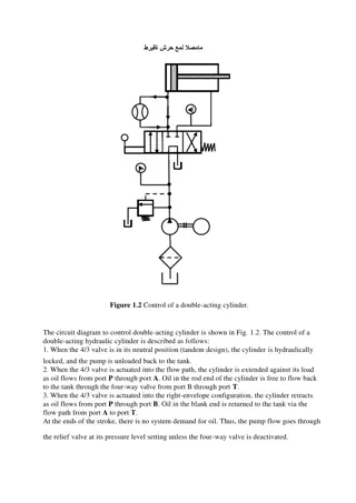
Piping and Tubing Symbols Normal working line Flexible working line Pilot line Drain line Enclosure outline Direction of flow
Crossing lines Joining lines
Reservoirs Open Sealed Reservoir Connecting lines above fluid level Connecting lines below fluid level
Fluid conditioning symbols are a diamond shape Basic filter/strainer Separator Manual Automatic Filter-separator
Cooler Liquid Gaseous Heater Temperature controlled
Pressure Nozzle Pressure Switch Temperature Flow meter, rate Float switch Flow meter, totalizing
Pumps Fixed displacement Unidirectional Bidirectional Variable displacement, non-compensated, unidirectional Variable displacement, non-compensated, bidirectional
Pumps Variable displacement, pressure-compensated, unidirectional Variable displacement, pressure-compensated, bidirectional M Electric Motor Internal combustion
Motors Fixed displacement, unidirectional Fixed displacement, bidirectional Variable displacement, unidirectional Variable displacement, bidirectional
Valves Normally closed, two-way, two port Normally closed, two-way, two position, two port Normally closed, four way, three position, four port
Valves Normally open, two-way, two position, two port Normally open, two-way, three position, three port Normally open, four way, infinite Normally open, four way, three position, four port position, four port
Relief Valve Spring loaded Valve normally closed Variable Pressure Side Valve is regulated by the feed pressure When open, goes to tank Represents the pilot line
Pressure Reducing Valve Spring loaded Valve normally open Variable Pressure Side Valve is regulated by the discharge pressure Discharge side goes to line Represents the pilot line
Valves Relief Valve Sequencing Valve Pressure Reducing/Regulating Valve
Valves Orifice V Timing logic Check valve
Valves Flow control with bypass, pressure compensated Flow control with bypass, pressure and temperature compensated
Valves Counterbalance Valve Unloading Valve
Controls Push Button Liquid pilot Lever Gas pilot Pedal Servo Cam Pilot or solenoid Pilot and solenoid activated, spring return Solenoid
Cylinders Single acting Double acting Single acting, spring return Double acting, double rod Double acting, single cushion Double acting, Double cushion Double acting, double adjustable cushion Ram Pressure intensifier Telescoping
This workforce solution was funded by a grant awarded by the U.S. Department of Labor s Employment and Training Administration. The solution was created by the grantee and does not necessarily reflect the official position of the U.S. Department of Labor. The Department of Labor makes no guarantees, warranties, or assurances of any kind, express or implied, with respect to such information, including any information on linked sites, but not limited to accuracy of the information or its completeness, timeliness, usefulness, adequacy, continued availability or ownership. This work is licensed under a Creative Commons CC BY 3.0 Unported License. http://creativecommons.org/licenses/by/3.0/
