Introduction to Properties of Fluids in Hydraulic Systems

1
Lecture 1
PROPERTIES OF FLUID
1.1
Introduction
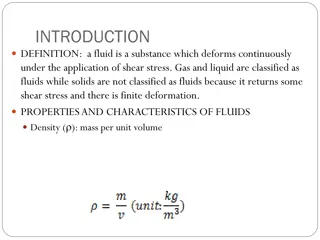
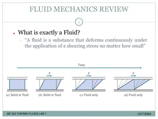
Fluids, both liquids and gases, are characterized by their continuous deformation
when a shear force, however small, is applied. Liquids and gases may be distinguished by
their relative incompressibilities and the fact that liquid may have a free surface while a gas
expands to fill its confining container. Because the liquid is the medium of transmission of
power in hydraulic system, knowledge of its characteristics is essential. The purpose of this
chapter is to define certain fundamental properties of fluids which will be useful to apply the
basic principles of fluid mechanics to the solution of practical problems on fluid power.
1.2 Solids and Fluids (Liquids and Gases)
1.2.1 Distinction between a Solid and a Fluid
The molecules of a solid are usually closer to each other than those of a fluid. The
attractive forces between the molecules of a solid are so large that a solid tends to retain its
shape. This is not the case with a fluid where the attractive forces between the molecules are
smaller. An ideal elastic solid deforms under load, and once the load is removed, it returns to
its original state.
1.2.2 Distinction between a Gas and a Liquid
A fluid may be either a gas or a liquid. The molecules of a gas are much farther a part
than those of a liquid. Hence, a gas is very compressible, and when all external pressure is
removed, it tends to expand indefinitely. A liquid is relatively incompressible, and if all
pressure, except its own vapor pressure, is removed, the cohesion between molecules holds
them together, so that the liquid does not expand indefinitely. Therefore, a liquid may have a
free surface, that is, a surface from which all pressure is removed, except its own vapor
pressure.
2
1.3 Density, Specific Weight, Specific Volume and Specific Gravity
1.3.1 Density
Density (
ρ
) is defined as mass per unit volume, that is,
(1.1)
The density characteristics of typical hydraulic fluids are given in Table 1.1.
Table 1.1
Density characteristics of hydraulic fluids
Fluid
Density
(kg/m )
3
Shell Tellus ISO 32 mineral oil
875
Shell HFB 60%oil,40%oil
933
Shell HFC 60%glycol,40%water
1084
Shell HFD phosphate ester
1125
Shell Naturelle HFE 32
918
It is well known that density increases with pressure and decreases with temperature. Figure
1.1shows such a characteristic for an ISO 32 mineral oil.
Figure 1.1
Characteristics of ISO 32 mineral oil.
3
1.3.2 Specific Weight
Specific weight (
γ
) is defined as weight per unit volume, that is,
(1.2)
Density and specific weight are related by
where
g
is acceleration due to gravity. Now
Note that the density (
ρ
) is absolute, since it depends on mass, which is independent of
location. The specific weight (
γ
), on the other hand, is not absolute, since it depends on the
value of gravitational acceleration (
g
), which varies with location, primarily latitude and
elevation above mean sea level. The densities and specific weights of fluids vary with
temperature. Table 1.2 gives specific weight of common fluids. The specific weight of a liquid
varies only slightly with pressure, depending on the bulk modulus of the liquid; it also
depends on temperature and the variation may be considerable. Since the specific weight (
γ
) is
equal to
ρ
g
, the specific weight of a fluid depends on the local value of the acceleration due to
gravity in addition to the variation in temperature and pressure.
4
Table 1.2
Specific weight (
γ
in kN/m ) of common liquids at 20°C, 1013 millibar abs with
g
=
3
9.81 m/s
2
Carbon tetrachloride
15.6
Ethyl alcohol
7.76
Gasoline
6.6
Glycerin
12.3
Kerosene
7.9
Motor oil
8.5
Seawater
10.03
Water
9.79
1.3.3 Specific Volume
Specific volume (SV) is the volume occupied by a unit mass of fluid. We commonly apply it
to gases and usually express it in m /kg. Specific volume is the reciprocal of density. Thus,
3
(1.3)
1.3.4 Specific Gravity
Specific gravity (SG) of a given fluid is defined as the specific weight of the fluid divided by
the specific weight of water, that is
5
(1.4)
SG of a liquid is a dimensionless ratio. Physicists use 4°C as the standard temperature, but
engineers often use 15.56°C. In the metric system, the density of water at 4°C is 1.00 g/cm ,
3
equivalent to 1000 kg/m , and hence the SG (which is dimensionless) of a liquid has the same
3
numerical value as its density expressed in g/mL or mg/m .
3
The SG of a gas is the ratio of its density to that of either hydrogen or air at some specified
temperature and pressure, but there is no general agreement on these standards, and so we
must explicitly state them in any given case. Since the density of a fluid varies with
temperature, we must determine and specify specific gravities at a particular temperature.
Example 1.1
Air at 20°C and atmospheric pressure has a density of 1.23 kg/m . Find its specific gravity.
3
What is the ratio of the specific gravity of water to the specific gravity of air at 20°C and
atmospheric pressure? What is the significance of the ratio?
Solution:
Given
T
= 20°C, air density
, water density
. Specific gravity of air is given by
We know that specific gravity of water = 1. So
Therefore, water is 813 times heavier than air.
Example1.2
The specific weight of oil mixture at ordinary pressure and temperature is 9.81 kN/m . The
3
specific gravity of mercury is 13.56. Compute the density of oil mixture and the specific
weight and density of mercury.
Solution:
Given specific weight of oil mixture
= 9.81. The density of oil is
6
The specific weight and density of mercury are, respectively,
Example 1.3
A cylinder container has a diameter of 0.5 m and a height of 1 m. If it is to be filled with a
liquid having a specific weight of 2000 N/m , how many kg of this liquid must be added?
3
Solution:
Given
. The volume is given by
Also it is given that specific weight (
γ
) is 2000 N/m . Now
3
The mass is given by
Example 1.4
One liter of SAE30 oil weighs 8.70 N. Calculate its specific weight, density and specific
gravity.
Solution:
Given
. The specific weight is
and mass density is
7
Therefore,
1.4
Pressure
Pressure is defined as force per unit area. It is the amount of force acting over a unit area, that
is
(1.5)
The pressure developed at the bottom of a column of any liquid is called hydrostatic pressure
and is given by
(1.6)
Since
and
where
γ
is the specific weight of liquid in N/m , we have
3
.
8
1.4.1 Pressure at the Bottom of a Column of Liquid
Let us now refer to Fig. 1.2, which shows the pressure head developed at the bottom due to
the column of liquid. Let
h
be the height of the liquid column and
W
be the weight of the
liquid. Let the liquid have a specific weight
and volume
V
:
(1.7)
Figure 1.2
Pressure developed by a column of fluid.
Observing the equation, it can be concluded that pressure does not depend on the cross-
sectional area of the liquid column but only on the column height and specific weight of the
liquid. Changing the cross-sectional area of the liquid column changes the weight of the liquid
by a proportional amount. Hence,
F
/
A
(pressure) remains constant.
1.4.2 Atmospheric Pressure and Absolute Pressure
Atmospheric pressure is the force per unit area exerted against a surface by the weight
of air above that surface in the Earth’s atmosphere. In most circumstances, atmospheric
pressure is closely approximated by the hydrostatic pressure caused by the weight of air above
the measurement point. Low-pressure areas have less atmospheric mass above their location,
whereas high-pressure areas have more atmospheric mass above their location. Similarly, as
elevation increases, there is less overlying atmospheric mass, such that the pressure decreases
with increasing elevation. The standard atmosphere is a unit of pressure that is equal to
h
P
9
101325 Pa or 101.325 kPa. The following units are equivalent, but only to the number of
decimal places displayed: 760 mmHg (torr), 29.92 in Hg, 14.696 psi, 1013.25 mbar/hPa. One
standard atmosphere is the standard pressure used for pneumatic fluid power (ISO R554) and
in the aerospace (ISO 2533) and petroleum (ISO 5024) industries. Absolute pressure is
measured relative to a perfect vacuum such as that existing in outer space.
1.4.3
Gauge pressure and absolute pressure
Gauge pressure is measured relative to the atmosphere, whereas absolute pressure is
measured relative to a perfect vacuum such as that existing in outer space.
A chart showing the difference between gauge and absolute pressure is given in Fig. 1.3. Let
us examine the two pressure levels
P
1 and
P
2.
1.
Relative to a prefect vacuum, they are:
•
P
1 = 0.7 bar (absolute), that is, a pressure less than an atmospheric pressure.
•
P
2 = 2 bar (absolute), that is, a pressure greater than an atmospheric pressure.
2.
Relative to atmosphere, they are:
•
P
1 = −0.3 bar (gauge, suction or vacuum).
•
P
2 = 1 bar (gauge).
As can be seen from Fig. 1.3, the following rule can be used in pressure conversion
calculations:
Absolute pressure = Gauge pressure + Atmospheric pressure
It should be noted that vacuum or suction pressures exist in a certain location of fluid power
systems (e.g., in the inlet or suction lines of pumps). Therefore, it is important to understand
the meaning of pressures below atmospheric pressure. One way to generate a suction pressure
is to remove some of the fluid from a closed vessel initially containing fluid at atmospheric
pressure.
10
Figure 1.3
Difference between absolute and gauge pressure.
Example 1.5
For the fluid power automobile lift system of Fig. 1.4, the hydraulic piston has a 250-mm
diameter. How much of oil pressure (kPa) is required to lift a 13300 N automobile?
Figure 1.4
2bar absolute
pressure
0.7 bar absolute
pressure
1 bar absolute
pressure
0.3 bar gaugepressure
Atmospheric pressure
Absolute zero pressure (complete
vacuum)
Zero-gauge pressure
1 bar gaugepressure
AIR
Air from
compressor
Control valve
Piston
OIL
11
1 m
AIR
Air from
compressor
Control valve
Piston
Oil
Solution:
Given force
F
= 13300 N, diameter (d) = 0.25 m, area (A) = 0.0491 m .The gauge
2
pressure is
Example 1.6
For the fluid power automobile lift system of Fig. 1.5, the air pressure equals 550 kPagauge. If
the hydraulic piston has a diameter of 250 mm, what is the maximum weight of an automobile
that can be lifted? The specific gravity of oil is 0.9. What percentage error in the answer to
this problem occurs by ignoring the 1-m head of oil to between the air and interface surface
and bottom surface of the piston?
.
Figure 1.5
Solution:
Given pressure of
air
. We know that
If we ignore 1-m oil head, then
Then, error in solution is calculated as
12
1.5 Compressible and Incompressible Fluids
Fluid power deals with both incompressible and compressible fluids, that is, with oil
and air of either constant or variable density. Although there is no such thing in reality as an
incompressible fluid, we use this term where the change in density with pressure is so small as
to be negligible. This is usually the case with liquids. We may also consider gases to be
incompressible when the pressure variation is small compared with the absolute pressure.
Ordinarily, we consider liquids to be incompressible fluids; yet sound waves, which are really
pressure waves, travel through them. This provides the evidence of the elasticity of liquids.
The flow of air in a ventilating system is a case where we may treat a gas as incompressible,
for the pressure variation is so small that the change in density is of no importance. However,
for a gas or steam flowing at a high velocity through a long pipeline, the decrease in pressure
may be so high that we cannot ignore the change in density. For an airplane flying at a speed
below 100 m/s, we may consider the air to be of constant density. But as an object moving
through air approaches the velocity of sound, which is of the order of 1200 km/h depending
on temperature, the pressure and density of the air adjacent to the body become materially
different from those of the air at some distance away.
1.6 Bulk Modulus (Volume Modulus of Elasticity)
Bulk modulus is a measure of the compressibility of a liquid and is required when it is
desired to calculate oil volume changes for high pressure and large system volumes such as
forging pressures or natural frequencies generally caused by the interaction of fluid
compressibility and moving mass. Bulk modulus is analogous to the modulus of elasticity for
solids; however, for fluids, it is defined on a volume basis rather than in terms of the familiar
one-dimension stress–strain relation. The compressibility (a change in volume due to a change
in pressure) of liquid is inversely proportional to its bulk modulus. For liquids, the value of
bulk modulus is 1.72 × 10
6
kPa
.
The volume modulus of mild steel is about 170000 MPa.
Taking a typical value for the volume modulus of cold water to be 2200 MPa, we see that
water is about 80 times as compressible as steel. The compressibility of liquids covers a wide
13
range. Mercury, for example, is approximately 8% as compressible as water, whereas the
compressibility of nitric acid is nearly six times that of water.
Example 1.7
A 500 cm sample of oil is to be compressed in a cylinder until its pressure is increased from 1
3
to 50 atm. If the bulk modulus of oil equals 1750 MPa, find the percentage change in its
volume.
Solution:
Given volume (
V
) = 500 cm ,
3
and
. We
know that
Reduction in volume = −0.2836 %, which implies that oil is incompressible.
Example 1.8
A positive displacement pump with a delivery of 1 L/min is fed into a pipe with a total volume
of 1 L. If the end of the pipe is suddenly blocked, calculate the rise in pressure after 1 s. (The
bulk modulus of the fluid being pumped may be taken as 2000 MPa; neglect any change in the
volume of the pipe.)
Solution:
Bulk modulus is given as
where Δ
P
is the change in pressure, Δ
V
is the change in volume and
V
is the original volume.
Now
Hence,
14
This rapid rise in pressure illustrates the necessity of having some form of control to limit the
rise in pressure in a system should a pump be deadheaded. The control may be built into the
pump or may be an external pressure-limiting device such as a relief valve.
Example 1.9
An 8 L sample of oil is compressed in a cylinder until pressure increases from 0.7 to 2.7 MPa.
If the bulk modulus equals 80 MPa, find the change in the volume of oil.
Solution:
Given initial volume
V
= 8 L = 0.008 m and change in pressure
∆P =
2.7 − 0.7 = 2
3
MPa. Bulk modulus is given by
So, change in volume
∆V
= −
V
= −0.008
= −0.002 m
3
1.7 Reynolds Number
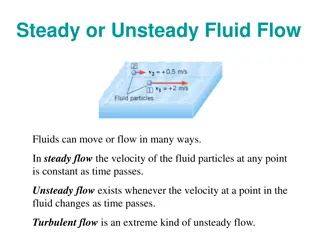
1.8 Types of Fluid Flow
Based on the range of Reynolds number, the flow of fluid is classified as laminar flow,
transition flow and turbulent flow.
15
1.
Laminar flow:
In the laminar flow region, the flow is characterized by the smooth motion
of the laminae or layers. When there is no macroscopic mixing of adjacent fluid layers for the
flow in the laminar regimes, the Reynolds number is less than 2000.
2.
Turbulent flow:
In the turbulent flow region, the flow is characterized by the random
motion of the fluid particles in three dimensions in addition to mean motion. There is
considerable macroscopic mixing of adjacent fluid layers and significant velocity fluctuations.
For the turbulent flow, the Reynolds number is greater than 4000.
3.
Transition flow:
In the transition flow region, the flow is in transition between laminar and
turbulent flows. The Reynolds number lies between 2000 and 4000.
1.9 Ideal Fluid
An ideal fluid is usually defined as a fluid in which there is no friction; it is inviscid
(its viscosity is zero). Thus, the internal forces at any section within it are always normal to
the section, even during motion. So these forces are purely pressure forces. Although such a
fluid does not exist in reality, many fluids approximate frictionless flow at a sufficient
distance from solid boundaries, and so we can often conveniently analyze their behaviors by
assuming an ideal fluid.
In a real fluid, either liquid or gas, tangential or shearing forces always develop whenever
there is a motion relative to body, thus creating fluid friction, because these forces oppose the
motion of one particle past another. These friction forces give rise to a fluid property called
viscosity.
1.10 Viscosity
The viscosity of a fluid is a measure of its resistance to shear or angular deformation.
Motor oil, for example, has a high viscosity and resistance to shear; it is cohesive and feels
“sticky,” whereas gasoline has a low viscosity. The friction forces in a flowing fluid result
from the cohesion and momentum which are interchangeable between molecules. The
viscosity of typical fluids depends on temperature. Figure 1.7 indicates how the viscosities of
16
typical fluids depend on temperature. As the temperature increases, the viscosities of all
liquids decrease, whereas the viscosities of all gases increase. This is because of the force of
cohesion, which diminishes with temperature, predominates with liquids, whereas with gases,
the predominating factor is the interchange of molecules between the layers of different
velocities. Thus, a rapidly moving gas molecule shifting into a slower moving layer tends to
speed up the latter, and a slow-moving molecule entering a faster moving layer tends to slow
down the faster moving layer. This molecular interchange sets up a shear or produces a
friction force between adjacent layers. At higher temperatures, molecular activity increases,
thereby causing the viscosity of gases to increase with temperature.
Figure 1.7
Trends in viscosity variation with temperature.
Consider a classic case of two parallel plates (Fig. 1.8), sufficiently large that we can neglect
edge conditions, a small distance
Y
apart, with fluid filling the space in between. The lower
plate is stationary whereas the upper one moves parallel to it with a velocity
U
due to a force
F
corresponding to some area
A
of the moving plate.
Temperature
Viscosity
Liquids
Gases
17
(a)
(b)
Figure 1.8
Velocity profiles across parallel plates: (a) Linear (no bulk flow) and (b)
linear (bulk flow to right).
At the boundaries, the particles of a fluid adhere to the walls, so their velocities are zero
relative to the walls. This is the so-called no-slip condition that occurs in all viscous fluids.
Thus, in Fig. 1.8, the fluid velocities must be
U
when in contact with the plate at the upper
boundary and zero at the lower boundary. We call the form of velocity variation with distance
between these two extremes, as depicted in Fig. 1.8, a
velocity profile
. If the separation
distance
Y
is not too large, the velocity profile is linear, as shown in Fig. 1.8(a). If, in addition,
there is a small amount of bulk fluid transport between the plates, which could result from
pressure-fed lubrication, for example, the velocity profile becomes the sum of the previous
linear profile and a parabolic profile as shown in Fig. 1.8(b); the parabolic additions to the
linear profile are zero at the walls and maximum at the centerline. The behavior of the fluid is
U
u
Y
y
F
,
U
Velocity Profile
Slope =
dy
/
dx
U
u
du
dy
Y
y
Velocity
profile
F
,
U
Upper Boundary
Lower Boundary
18
much as if it is consisted of a series of thin layers, each of which slips a little relative to the
next.
For a large class of fluids under the conditions of Fig. 1.8(a), experiments have shown that
We see from similar triangles that we can replace
U
/
Y
by the velocity gradient
du
/
dy
. If we
now introduce a constant of proportionality
µ
, we can express the shearing stress
τ
between
any two thin sheets of fluid by
(1.8)
This equation is called Newton’s equation of viscosity, since Sir Isaac Newton (1642–1727)
first suggested it. Although better known for this formulation of the fundamental laws of
motion and gravity for the development of differential calculus, Newton, an English
mathematician and natural philosopher, also performed many pioneering studies in fluid
mechanics. In transposed form, Eq. (1.8) defines the proportionality constant
where
is known as the coefficient of viscosity, the dynamic viscosity or simply the
viscosity of the fluid. “Absolute viscosity” shall be used to help differ entiate it from another
viscosity that will be discussed shortly.
In the beginning of this lecture, we noted that the distinction between a solid and a fluid lies in
the manner in which each can resist shearing stress. A further distinction among various kinds
of fluids and solids will be clarified by referring to Fig. 1.9. In the case of a solid, shear stress
depends on the magnitude of the deformation, but Eq. (1.8) shows that in many fluids, shear
stress is proportional to the time rate of deformation.
19
Figure 1.9
Velocity profiles – linear (bulk flow to right).
A fluid for which the constant of proportionality does not change with the rate of deformation
is called a Newtonian fluid, and this is plotted as a straight line in Fig. 1.9. The slope of this
line is the absolute viscosity
µ
. The ideal fluid with no viscosity falls on the horizontal axis,
whereas a true elastic solid is plotted on the vertical axis. A plastic that sustains a certain
amount of stress before suffering a plastic flow corresponds to a straight line intersecting the
vertical axis at the yield stress. There are certain non-Newtonian fluids in which
µ
varies with
the rate of deformation. These are relatively uncommon in engineering usage, so we restrict
the remainder of this text to the common fluids that under normal conditions obey Newton’s
equation of viscosity. Note that
A widely used unit of viscosity in the metric system is the poise (P) named after Jean Louis
Poiseuille (1799–1869). Poiseuille, a French anatomist, was one of the first investigators of
viscosity. A poise = 0.10 Ns/m . A centipoise (=0.01 P) is frequently a more convenient unit.
2
It has a further advantage in that the viscosity of water at 20.2°C is 1 cP. Thus, the value of
viscosity in centipoise is an indication of the viscosity of a fluid relative to that of water at
20.2°C.
du/dy
Elastic solid
Newtonian fluid
Non-Newtonian fluid
Ideal plastic
Ideal fluid
Shear stress (
)
20
In many problems involving viscosity, the absolute viscosity is divided by density. This ratio
defines the kinematic viscosity,
<COMP: Greek letter nu>, so called because force is not
involved, the only dimensions being length and time, as in kinematics. Thus,
(1.9)
Usually, the kinematic viscosity (
) is measured in m /s. Previously, in the metric system, the
2
common units were cm /s, also called the stoke (St), after Sir George Stokes (1819–1903), an
2
English physicist and pioneering investigator of viscosity. Many physicists found centistoke
(cSt) a more convenient unit to work with.
A comparison of kinematic viscosities of fluids is shown in Fig. 1.10(a) for low operating
pressures. A more detailed characteristic of an ISO 32 mineral oil is shown in Fig. 1.10(b),
illustrating the important effect of both temperature and pressure. The data shown in Fig. 1.10
make it clear that experimental testing must specify both pressure and temperature so that
related studies may be compared with at least a minimum of confidence. It is common that
computer dynamic simulations of hydraulic systems usually assume a mean temperature in a
sense that the temperature does not vary significantly during the milliseconds to second of
transient behavior. However, it may be necessary to model the effect of pressure on viscosity
if large fluctuations in pressure are expected, although its effect may well be of secondary
significance.
21
(a)
(b)
Figure 1.10
Typical kinematic viscosities for a range of fluids. (a) Some fire-resistant fluids.
(b) An ISO 32 mineral oil.
22
Example 1.11
A 4.5 N force moves a piston inside a cylinder at a velocity of 3 m/s as shown in Fig. 1.11.
The piston of 10.16 cm diameter is centrally located in the cylinder having an internal
diameter of 10.17 cm. An oil film separates the piston from the cylinder. Find the absolute
viscosity of the oil.
Figure 1.11
Solution:
Given force on the piston = 4.5 N, piston diameter (
d
) =10.16 cm, velocity (
v
) = 3
m/s, cylinder diameter (
D
) = 10.17 cm and length (
L
) = 5 cm. Using Newton’s law of
viscosity we have
For small gaps,
(1.10)
Now we have
=
Piston
F
= 4.5 N
v
= 3 m/s
50 mm
23
Substituting in Eq. (1.10) we get
Since 1 N =
we get
24
Figure 1.12
25
1.11 The Saybolt viscometer
The instruments used to measure the viscosity of a liquid are known as viscometers or
viscosimeters. Several types of viscosimeters are in use today. The Saybolt viscometer
measures the time required, in seconds, for 60 milliliters of the tested fluid at 100 °F
to pass through a standard orifice. The time measured is used to express the fluid’s
viscosity, in Saybolt universal seconds or Saybolt furol seconds as described in
Fig.1.13.
1.12 Viscosity Index
The viscosity of hydraulic oils decreases with increase in temperature. Hence, the viscosity of
the given oil must be represented at a special temperature. The variation of viscosity with
respect to temperature is different for different oils.
The viscosity index (VI) is a relative measure of the change in the viscosity of an oil with
respect to a change in temperature. An oil having a low VI is one that exhibits a large change
26
Figure 1.13
in viscosity with a small change in temperature. A high VI oil does not change appreciably
with a change in temperature.
The VI of any hydraulic oil can be calculated as follows:
(1.11)
where
L
is the viscosity in SUS (Saybolt universal viscosity)of a 0 VI oil at 100°F,
U
is the
viscosity in SUS of an unknown VI oil at 100°F and
H
is the viscosity in SUS of a 100 VI oil
at 100 °F. The VI of an unknown oil is determined from tests. A reference oil of 0 VI and a
reference oil of 100 VI are selected. The viscosities of three oils (
L
,
U
and
H
) are then
measured at 100°F.This is shown schematically in Fig. 1.13.
27
A high VI oil is a good all-weather-type oil for use in outdoor machines operating in extreme
temperature swings. For a hydraulic system, the oil temperature does not change appreciably;
hence, the VI of the oil is not crucial.
Figure 1.13
Viscosity index.
Example 1.13
A sample of oil with viscosity index of 70 is tested with a 0 VI oil and a 100 VI oil whose
viscosity values at 100°F are 375 and 125 SUS, respectively. What is the viscosity of the
sample oil at 100°F in units of SUS?
Solution:
We know that
100
210
L
U
H
100 VI oil
Zero VI oil
Unknown VI oil
Temperature (
Viscosity (SUS)
28
where
L
is the viscosity of 0 VI oil at 100F,
H
is the viscosity of 100 VI oil at 100F, and
U
is the required viscosity in SUS So,
Example 1.14
A sample oil is tested with a 0 VI oil and a 100 VI oil whose viscosity values at 38°C are 400
and 150 SUS, respectively. If the viscosity of the sample oil at 38°C is 200 SSU, what is the
viscosity index of the sample oil?
Solution:
We know that
VI of the sample oil =
× 100 =
× 100
=
× 100 = 80 VI
1.13 Hydraulic Fluid
Hydraulic system liquids are used primarily to transmit and distribute forces to various
units to be actuated. Liquids are able to do this
because they are almost
incompressible. Pascal’s Law states that pressure applied to any part of a confined
liquid is transmitted with undiminished intensity to every other part. Thus, if a number
of passages exist in a system, pressure can be distributed through all of them by means
of the liquid.
The demands placed on hydraulic systems constantly change as industry requires
greater efficiency and speed at higher operating temperatures and pressures. Selecting
the best hydraulic fluid requires a basic understanding of each particular fluid's
characteristics in comparison with an ideal fluid. An ideal fluid would have these
characteristics:
29
1. Thermal stability
2. Hydrolytic stability
3. Low chemical corrosiveness
4. High anti-wear characteristics
5. Low tendency to cavitate
6. Long life
7. Total water rejection
8. Constant viscosity, regardless of temperature, and
9. Low cost.
Although no single fluid has all of these ideal characteristics, it is possible to select one that is
the best compromise for a particular hydraulic system. This selection requires knowledge of
the system in which a hydraulic fluid will be used. The designer should know such basic
characteristics of the system as:
1.
Maximum and minimum operating and ambient temperatures
2.
Type of pump or pumps used
3. Operating pressures
4. Operating cycle
5.
Loads encountered by various components, and
6.
Type of control and power valves.
30
1.14 Hydraulic fluid types
The hydraulic fluids are broadly classified into three categories based on major
constituents:
1) Petroleum Based Fluids.
2) Synthetic Based Fluids.
3) Water Based Fluids.
1.14.1 Petroleum Based Fluids
The petroleum base fluids are most commonly used fluids. The additives are
added, to avoid oxidation , reduce foaming and to improve viscosity. Besides the
additives are contributing in: -
1) Decrease corrosion
2) Increase life duration
3) Improve temperature dependence of viscosity
4) Improve particle transport
The advantages of petroleum base fluids are:
1) Protection against rust
2) Better sealing property
3) Better heat dissipating effects
4) Low density and light weight
The Disadvantages of petroleum base fluids are:
1) High cost.
31
2) Low
flash
point.
(
The flash
point of
a
volatile
material
is
the
lowest
temperature
at which vapors of the material will ignite, when given an
ignition source.)
3) Highly inflammable.
1.14.2 Synthetic Based Fluids
These types of fluids do not contain water or volatile material. The Chemical
stability of these fluids is very good and they can be used for very high temperature
and pressure applications. These fluids are prepared in laboratory from many types
such as; Phosphate esters, Halogenated hydrocarbons, silicon synthetic fluid.
The advantages of this type are:
1) Less inflammable compared to petroleum based oils
2) Can operate at higher temperatures (1500 C)
3) Useful in high pressure system
Disadvantages:
1) Performance is poor at low temperatures; hence external heating has to be
done.
2) Viscosity index is low.
3) Specific gravity is high, requiring high pumping power.
1.14.3 Water Based Fluids
This type of fluids is made from clear water with additives. The water is about (90-95
%), whereas the additives (5-10 %). They used when there is an explosion or fire
32
danger or hygiene problem such in Food and Pharmaceutical industry, textile industry,
mining.
The advantages of these fluids are:
1) Low viscosity and it does not change very much over a large temperature
range.
2) Abundantly available and cheap
3) Highly non-inflammable and cannot catch fire.
4) Very good chemical stability over a wide range of temperature
5) Not slippery when leaked.
Disadvantages:
1) Operating temperature range is limited.
2) Highly corrosive.
3) Low lubricating properties.
4) Water in its pure form can never give the necessary benefit. The advantages
can be employed by making High Water Based Fluids (HWBF)
1.15 Fluid requirements
The hydraulic fluid should include the following characteristics to best use:
1- Lubrication and anti-wear characteristics
The fluid must be capable to covering all moving parts with tenacious
lubricant film. The lubricant film may be destroyed, as result of high pressure,
33
insufficient oil delivery, low velocity and either slow or very fast sliding
movements. This would result in wear due to fretting.
2- Compatibility with different materials
The fluid must be fully compatible with other materials used in hydraulic
systems, such as those used for bearing, seals, paints, etc. Where, the fluid
leaks out from the hydraulic system and comes into contact with other system
parts, such as electrical lines, mechanical components, etc. the fluid must also
be compatible with these parts.
3- Stability against shearing
Fluids become mechanically loaded, when they reach control lands and on the
opening and closing of valve seats. The fluid flow is then “sheared”. This
process effects the service life of a fluid. So , the fluid should contains
viscosity index enhancers to increase the sensitivity to shearing .
4- Stability against thermal loads
The temperature of the fluid may increase during system operation. When the
system is idle, the temperature is reduced again. This repetitive process
influences the service life of the fluid. Hence in many systems, the operating
temperature of the fluid is kept constant by using heat exchangers.
5- Stability against oxidation
The ageing process in mineral oils influenced by oxygen, heat, light and
catalysis. A mineral oil with a better ageing characteristic, has oxidation
inhibitors in it, which prevent oxygen from being quickly absorbed. Increased
absorption of oxygen would in addition lead to an increase in the corrosion of
components.
34
6- Low compressibility
The dissolved air carried along in the fluid determines how much fluid column
is compressed. This characteristic influences the accuracy of hydraulic drives.
In open and closed loop control process, compressibility influences response
time.
If
large
volumes
trapped
under
pressure
are
quickly opened,
decomposition shocks occur in the system.
7- Little formation of foam
Rising air bubbles may form foam on the surface in a tank. The formation of
foam may be minimized by correctly arranging the return lines in the tank and
by proper construction of the tank, e.g. by installing baffles. Mineral oils
contain chemical additives, which reduce foam. The tendency for a fluid to
form foam increases with age, contamination
and condensation
.
8- Little expansion due to temperature
If the temperature of the fluid increases due to atmospheric pressure, the
volume of fluid increases. If large quantity of fluid is to be used in a system, the
operating temperature of the system must be considered. For example, the
volume of mineral oil increases by 0.7% for each 10 C.
o
9- High boiling point and low steam pressure
The higher the boiling point of the fluid used, the maximum operating
temperature of the system may be used.
10-
Good thermal conductivity
Heat created in pumps, valves, motors, cylinders and pipes should be
transported by the fluid to tank. The heat returned to the tank is partly removed
to the outside through the walls of the tank. if the radiation surfaces are not
sufficient, additional heat exchangers
Fluids, including liquids and gases, exhibit continuous deformation when subjected to shear forces. Understanding fundamental properties like density, specific weight, and specific volume is crucial for applying fluid mechanics principles to solve practical problems in fluid power systems. This chapter discusses the distinctions between solids, liquids, and gases, emphasizing the importance of fluid characteristics in hydraulic applications.

Download Presentation

Please find below an Image/Link to download the presentation.
The content on the website is provided AS IS for your information and personal use only. It may not be sold, licensed, or shared on other websites without obtaining consent from the author. Download presentation by click this link. If you encounter any issues during the download, it is possible that the publisher has removed the file from their server.
E N D
Presentation Transcript
1 Lecture 1 PROPERTIES OF FLUID 1.1 Introduction Fluids, both liquids and gases, are characterized by their continuous deformation when a shear force, however small, is applied. Liquids and gases may be distinguished by their relative incompressibilities and the fact that liquid may have a free surface while a gas expands to fill its confining container. Because the liquid is the medium of transmission of power in hydraulic system, knowledge of its characteristics is essential. The purpose of this chapter is to define certain fundamental properties of fluids which will be useful to apply the basic principles of fluid mechanics to the solution of practical problems on fluid power. 1.2 Solids and Fluids (Liquids and Gases) 1.2.1 Distinction between a Solid and a Fluid The molecules of a solid are usually closer to each other than those of a fluid. The attractive forces between the molecules of a solid are so large that a solid tends to retain its shape. This is not the case with a fluid where the attractive forces between the molecules are smaller. An ideal elastic solid deforms under load, and once the load is removed, it returns to its original state. 1.2.2 Distinction between a Gas and a Liquid A fluid may be either a gas or a liquid. The molecules of a gas are much farther a part than those of a liquid. Hence, a gas is very compressible, and when all external pressure is removed, it tends to expand indefinitely. A liquid is relatively incompressible, and if all pressure, except its own vapor pressure, is removed, the cohesion between molecules holds them together, so that the liquid does not expand indefinitely. Therefore, a liquid may have a free surface, that is, a surface from which all pressure is removed, except its own vapor pressure.
2 1.3 Density, Specific Weight, Specific Volume and Specific Gravity 1.3.1 Density Density ( ) is defined as mass per unit volume, that is, (1.1) The density characteristics of typical hydraulic fluids are given in Table 1.1. Table 1.1 Density characteristics of hydraulic fluids Density (kg/m ) 3 875 Fluid Shell Tellus ISO 32 mineral oil Shell HFB 60%oil,40%oil Shell HFC 60%glycol,40%water Shell HFD phosphate ester Shell Naturelle HFE 32 933 1084 1125 918 It is well known that density increases with pressure and decreases with temperature. Figure 1.1shows such a characteristic for an ISO 32 mineral oil. Figure 1.1 Characteristics of ISO 32 mineral oil.
3 1.3.2 Specific Weight Specific weight ( ) is defined as weight per unit volume, that is, (1.2) Density and specific weight are related by where g is acceleration due to gravity. Now Note that the density ( ) is absolute, since it depends on mass, which is independent of location. The specific weight ( ), on the other hand, is not absolute, since it depends on the value of gravitational acceleration (g), which varies with location, primarily latitude and elevation above mean sea level. The densities and specific weights of fluids vary with temperature. Table 1.2 gives specific weight of common fluids. The specific weight of a liquid varies only slightly with pressure, depending on the bulk modulus of the liquid; it also depends on temperature and the variation may be considerable. Since the specific weight ( ) is equal to g, the specific weight of a fluid depends on the local value of the acceleration due to gravity in addition to the variation in temperature and pressure.
4 Table 1.2 Specific weight ( in kN/m ) of common liquids at 20 C, 1013 millibar abs with g = 3 9.81 m/s2 Carbon tetrachloride 15.6 Ethyl alcohol 7.76 Gasoline 6.6 Glycerin 12.3 Kerosene 7.9 Motor oil 8.5 Seawater 10.03 Water 9.79 1.3.3 Specific Volume Specific volume (SV) is the volume occupied by a unit mass of fluid. We commonly apply it to gases and usually express it in m /kg. Specific volume is the reciprocal of density. Thus, 3 (1.3) 1.3.4 Specific Gravity Specific gravity (SG) of a given fluid is defined as the specific weight of the fluid divided by the specific weight of water, that is
5 (1.4) SG of a liquid is a dimensionless ratio. Physicists use 4 C as the standard temperature, but engineers often use 15.56 C. In the metric system, the density of water at 4 C is 1.00 g/cm ,3 equivalent to 1000 kg/m , and hence the SG (which is dimensionless) of a liquid has the same 3 3 numerical value as its density expressed in g/mL or mg/m . The SG of a gas is the ratio of its density to that of either hydrogen or air at some specified temperature and pressure, but there is no general agreement on these standards, and so we must explicitly state them in any given case. Since the density of a fluid varies with temperature, we must determine and specify specific gravities at a particular temperature. Example 1.1 3 Air at 20 C and atmospheric pressure has a density of 1.23 kg/m . Find its specific gravity. What is the ratio of the specific gravity of water to the specific gravity of air at 20 C and atmospheric pressure? What is the significance of the ratio? Solution: GivenT = 20 C, air density , water density . Specific gravity of air is given by We know that specific gravity of water = 1. So Therefore, water is 813 times heavier than air. Example1.2 The specific weight of oil mixture at ordinary pressure and temperature is 9.81 kN/m . The specific gravity of mercury is 13.56. Compute the density of oil mixture and the specific weight and density of mercury. 3 Solution: Given specific weight of oil mixture = 9.81. The density of oil is
6 The specific weight and density of mercury are, respectively, Example 1.3 A cylinder container has a diameter of 0.5 m and a height of 1 m. If it is to be filled with a liquid having a specific weight of 2000 N/m , how many kg of this liquid must be added? 3 Solution: Given . The volume is given by 3 Also it is given that specific weight ( ) is 2000 N/m . Now The mass is given by Example 1.4 One liter of SAE30 oil weighs 8.70 N. Calculate its specific weight, density and specific gravity. Solution: Given . The specific weight is and mass density is
7 Therefore, 1.4 Pressure Pressure is defined as force per unit area. It is the amount of force acting over a unit area, that is (1.5) The pressure developed at the bottom of a column of any liquid is called hydrostatic pressure and is given by (1.6) Since and 3 where is the specific weight of liquid in N/m , we have .
8 1.4.1 Pressure at the Bottom of a Column of Liquid Let us now refer to Fig. 1.2, which shows the pressure head developed at the bottom due to the column of liquid. Let h be the height of the liquid column and W be the weight of the liquid. Let the liquid have a specific weight and volume V: P h (1.7) Figure 1.2 Pressure developed by a column of fluid. Observing the equation, it can be concluded that pressure does not depend on the cross- sectional area of the liquid column but only on the column height and specific weight of the liquid. Changing the cross-sectional area of the liquid column changes the weight of the liquid by a proportional amount. Hence, F/A (pressure) remains constant. 1.4.2 Atmospheric Pressure and Absolute Pressure Atmospheric pressure is the force per unit area exerted against a surface by the weight of air above that surface in the Earth s atmosphere. In most circumstances, atmospheric pressure is closely approximated by the hydrostatic pressure caused by the weight of air above the measurement point. Low-pressure areas have less atmospheric mass above their location, whereas high-pressure areas have more atmospheric mass above their location. Similarly, as elevation increases, there is less overlying atmospheric mass, such that the pressure decreases with increasing elevation. The standard atmosphere is a unit of pressure that is equal to
9 101325 Pa or 101.325 kPa. The following units are equivalent, but only to the number of decimal places displayed: 760 mmHg (torr), 29.92 in Hg, 14.696 psi, 1013.25 mbar/hPa. One standard atmosphere is the standard pressure used for pneumatic fluid power (ISO R554) and in the aerospace (ISO 2533) and petroleum (ISO 5024) industries. Absolute pressure is measured relative to a perfect vacuum such as that existing in outer space. 1.4.3 Gauge pressure and absolute pressure Gauge pressure is measured relative to the atmosphere, whereas absolute pressure is measured relative to a perfect vacuum such as that existing in outer space. A chart showing the difference between gauge and absolute pressure is given in Fig. 1.3. Let us examine the two pressure levels P1 and P2. 1. Relative to a prefect vacuum, they are: P1 = 0.7 bar (absolute), that is, a pressure less than an atmospheric pressure. P2 = 2 bar (absolute), that is, a pressure greater than an atmospheric pressure. 2. Relative to atmosphere, they are: P1 = 0.3 bar (gauge, suction or vacuum). P2 = 1 bar (gauge). As can be seen from Fig. 1.3, the following rule can be used in pressure conversion calculations: Absolute pressure = Gauge pressure + Atmospheric pressure It should be noted that vacuum or suction pressures exist in a certain location of fluid power systems (e.g., in the inlet or suction lines of pumps). Therefore, it is important to understand the meaning of pressures below atmospheric pressure. One way to generate a suction pressure is to remove some of the fluid from a closed vessel initially containing fluid at atmospheric pressure.
10 1 bar gaugepressure Atmospheric pressure Zero-gauge pressure 0.3 bar gaugepressure 2bar absolute pressure 1 bar absolute pressure 0.7 bar absolute pressure Absolute zero pressure (complete vacuum) Figure 1.3 Difference between absolute and gauge pressure. Example 1.5 For the fluid power automobile lift system of Fig. 1.4, the hydraulic piston has a 250-mm diameter. How much of oil pressure (kPa) is required to lift a 13300 N automobile? Control valve Air from compressor Piston AIR OIL Figure 1.4
11 2 Solution: Given force F = 13300 N, diameter (d) = 0.25 m, area (A) = 0.0491 m .The gauge pressure is Example 1.6 For the fluid power automobile lift system of Fig. 1.5, the air pressure equals 550 kPagauge. If the hydraulic piston has a diameter of 250 mm, what is the maximum weight of an automobile that can be lifted? The specific gravity of oil is 0.9. What percentage error in the answer to this problem occurs by ignoring the 1-m head of oil to between the air and interface surface and bottom surface of the piston? . Control valve Air from compressor Piston 1 m AIR Oil Figure 1.5 Solution: Given pressure of air . We know that If we ignore 1-m oil head, then Then, error in solution is calculated as
12 1.5 Compressible and Incompressible Fluids Fluid power deals with both incompressible and compressible fluids, that is, with oil and air of either constant or variable density. Although there is no such thing in reality as an incompressible fluid, we use this term where the change in density with pressure is so small as to be negligible. This is usually the case with liquids. We may also consider gases to be incompressible when the pressure variation is small compared with the absolute pressure. Ordinarily, we consider liquids to be incompressible fluids; yet sound waves, which are really pressure waves, travel through them. This provides the evidence of the elasticity of liquids. The flow of air in a ventilating system is a case where we may treat a gas as incompressible, for the pressure variation is so small that the change in density is of no importance. However, for a gas or steam flowing at a high velocity through a long pipeline, the decrease in pressure may be so high that we cannot ignore the change in density. For an airplane flying at a speed below 100 m/s, we may consider the air to be of constant density. But as an object moving through air approaches the velocity of sound, which is of the order of 1200 km/h depending on temperature, the pressure and density of the air adjacent to the body become materially different from those of the air at some distance away. 1.6 Bulk Modulus (Volume Modulus of Elasticity) Bulk modulus is a measure of the compressibility of a liquid and is required when it is desired to calculate oil volume changes for high pressure and large system volumes such as forging pressures or natural frequencies generally caused by the interaction of fluid compressibility and moving mass. Bulk modulus is analogous to the modulus of elasticity for solids; however, for fluids, it is defined on a volume basis rather than in terms of the familiar one-dimension stress strain relation. The compressibility (a change in volume due to a change in pressure) of liquid is inversely proportional to its bulk modulus. For liquids, the value of bulk modulus is 1.72 10 Taking a typical value for the volume modulus of cold water to be 2200 MPa, we see that water is about 80 times as compressible as steel. The compressibility of liquids covers a wide 6kPa. The volume modulus of mild steel is about 170000 MPa.
13 range. Mercury, for example, is approximately 8% as compressible as water, whereas the compressibility of nitric acid is nearly six times that of water. Example 1.7 A 500 cm sample of oil is to be compressed in a cylinder until its pressure is increased from 1 3 to 50 atm. If the bulk modulus of oil equals 1750 MPa, find the percentage change in its volume. 3 Solution: Given volume (V) = 500 cm , and . We know that Reduction in volume = 0.2836 %, which implies that oil is incompressible. Example 1.8 A positive displacement pump with a delivery of 1 L/min is fed into a pipe with a total volume of 1 L. If the end of the pipe is suddenly blocked, calculate the rise in pressure after 1 s. (The bulk modulus of the fluid being pumped may be taken as 2000 MPa; neglect any change in the volume of the pipe.) Solution: Bulk modulus is given as where P is the change in pressure, V is the change in volume and V is the original volume. Now Hence,
14 This rapid rise in pressure illustrates the necessity of having some form of control to limit the rise in pressure in a system should a pump be deadheaded. The control may be built into the pump or may be an external pressure-limiting device such as a relief valve. Example 1.9 An 8 L sample of oil is compressed in a cylinder until pressure increases from 0.7 to 2.7 MPa. If the bulk modulus equals 80 MPa, find the change in the volume of oil. Solution: Given initial volume V = 8 L = 0.008 m and change in pressure P =2.7 0.7 = 2 3 MPa. Bulk modulus is given by So, change in volume = 0.002 m3 V = V = 0.008 1.7 Reynolds Number 1.8 Types of Fluid Flow Based on the range of Reynolds number, the flow of fluid is classified as laminar flow, transition flow and turbulent flow.
15 1. Laminar flow: In the laminar flow region, the flow is characterized by the smooth motion of the laminae or layers. When there is no macroscopic mixing of adjacent fluid layers for the flow in the laminar regimes, the Reynolds number is less than 2000. 2. Turbulent flow: In the turbulent flow region, the flow is characterized by the random motion of the fluid particles in three dimensions in addition to mean motion. There is considerable macroscopic mixing of adjacent fluid layers and significant velocity fluctuations. For the turbulent flow, the Reynolds number is greater than 4000. 3. Transition flow: In the transition flow region, the flow is in transition between laminar and turbulent flows. The Reynolds number lies between 2000 and 4000. 1.9 Ideal Fluid An ideal fluid is usually defined as a fluid in which there is no friction; it is inviscid (its viscosity is zero). Thus, the internal forces at any section within it are always normal to the section, even during motion. So these forces are purely pressure forces. Although such a fluid does not exist in reality, many fluids approximate frictionless flow at a sufficient distance from solid boundaries, and so we can often conveniently analyze their behaviors by assuming an ideal fluid. In a real fluid, either liquid or gas, tangential or shearing forces always develop whenever there is a motion relative to body, thus creating fluid friction, because these forces oppose the motion of one particle past another. These friction forces give rise to a fluid property called viscosity. 1.10 Viscosity The viscosity of a fluid is a measure of its resistance to shear or angular deformation. Motor oil, for example, has a high viscosity and resistance to shear; it is cohesive and feels sticky, whereas gasoline has a low viscosity. The friction forces in a flowing fluid result from the cohesion and momentum which are interchangeable between molecules. The viscosity of typical fluids depends on temperature. Figure 1.7 indicates how the viscosities of
16 typical fluids depend on temperature. As the temperature increases, the viscosities of all liquids decrease, whereas the viscosities of all gases increase. This is because of the force of cohesion, which diminishes with temperature, predominates with liquids, whereas with gases, the predominating factor is the interchange of molecules between the layers of different velocities. Thus, a rapidly moving gas molecule shifting into a slower moving layer tends to speed up the latter, and a slow-moving molecule entering a faster moving layer tends to slow down the faster moving layer. This molecular interchange sets up a shear or produces a friction force between adjacent layers. At higher temperatures, molecular activity increases, thereby causing the viscosity of gases to increase with temperature. Gases Viscosity Liquids Temperature Figure 1.7Trends in viscosity variation with temperature. Consider a classic case of two parallel plates (Fig. 1.8), sufficiently large that we can neglect edge conditions, a small distance Y apart, with fluid filling the space in between. The lower plate is stationary whereas the upper one moves parallel to it with a velocity U due to a force F corresponding to some area A of the moving plate.
17 U F,U Upper Boundary dy Velocity profile Y Lower Boundary y u du (a) U F, U u Velocity Profile Y y Slope = dy/dx (b) Figure 1.8Velocity profiles across parallel plates: (a) Linear (no bulk flow) and (b) linear (bulk flow to right). At the boundaries, the particles of a fluid adhere to the walls, so their velocities are zero relative to the walls. This is the so-called no-slip condition that occurs in all viscous fluids. Thus, in Fig. 1.8, the fluid velocities must be U when in contact with the plate at the upper boundary and zero at the lower boundary. We call the form of velocity variation with distance between these two extremes, as depicted in Fig. 1.8, a velocity profile. If the separation distance Y is not too large, the velocity profile is linear, as shown in Fig. 1.8(a). If, in addition, there is a small amount of bulk fluid transport between the plates, which could result from pressure-fed lubrication, for example, the velocity profile becomes the sum of the previous linear profile and a parabolic profile as shown in Fig. 1.8(b); the parabolic additions to the linear profile are zero at the walls and maximum at the centerline. The behavior of the fluid is
18 much as if it is consisted of a series of thin layers, each of which slips a little relative to the next. For a large class of fluids under the conditions of Fig. 1.8(a), experiments have shown that We see from similar triangles that we can replace U/Y by the velocity gradient du/dy. If we now introduce a constant of proportionality , we can express the shearing stress between any two thin sheets of fluid by (1.8) This equation is called Newton s equation of viscosity, since Sir Isaac Newton (1642 1727) first suggested it. Although better known for this formulation of the fundamental laws of motion and gravity for the development of differential calculus, Newton, an English mathematician and natural philosopher, also performed many pioneering studies in fluid mechanics. In transposed form, Eq. (1.8) defines the proportionality constant where is known as the coefficient of viscosity, the dynamic viscosity or simply the viscosity of the fluid. Absolute viscosity shall be used to help differ entiate it from another viscosity that will be discussed shortly. In the beginning of this lecture, we noted that the distinction between a solid and a fluid lies in the manner in which each can resist shearing stress. A further distinction among various kinds of fluids and solids will be clarified by referring to Fig. 1.9. In the case of a solid, shear stress depends on the magnitude of the deformation, but Eq. (1.8) shows that in many fluids, shear stress is proportional to the time rate of deformation.
19 Elastic solid Shear stress ( ) Newtonian fluid Non-Newtonian fluid Ideal plastic Ideal fluid du/dy Figure 1.9Velocity profiles linear (bulk flow to right). A fluid for which the constant of proportionality does not change with the rate of deformation is called a Newtonian fluid, and this is plotted as a straight line in Fig. 1.9. The slope of this line is the absolute viscosity . The ideal fluid with no viscosity falls on the horizontal axis, whereas a true elastic solid is plotted on the vertical axis. A plastic that sustains a certain amount of stress before suffering a plastic flow corresponds to a straight line intersecting the vertical axis at the yield stress. There are certain non-Newtonian fluids in which varies with the rate of deformation. These are relatively uncommon in engineering usage, so we restrict the remainder of this text to the common fluids that under normal conditions obey Newton s equation of viscosity. Note that A widely used unit of viscosity in the metric system is the poise (P) named after Jean Louis Poiseuille (1799 1869). Poiseuille, a French anatomist, was one of the first investigators of viscosity. A poise = 0.10 Ns/m . A centipoise (=0.01 P) is frequently a more convenient unit. 2 It has a further advantage in that the viscosity of water at 20.2 C is 1 cP. Thus, the value of viscosity in centipoise is an indication of the viscosity of a fluid relative to that of water at 20.2 C.
20 In many problems involving viscosity, the absolute viscosity is divided by density. This ratio defines the kinematic viscosity,<COMP: Greek letter nu>, so called because force is not involved, the only dimensions being length and time, as in kinematics. Thus, (1.9) 2 Usually, the kinematic viscosity ( ) is measured in m /s. Previously, in the metric system, the common units were cm /s, also called the stoke (St), after Sir George Stokes (1819 1903), an 2 English physicist and pioneering investigator of viscosity. Many physicists found centistoke (cSt) a more convenient unit to work with. A comparison of kinematic viscosities of fluids is shown in Fig. 1.10(a) for low operating pressures. A more detailed characteristic of an ISO 32 mineral oil is shown in Fig. 1.10(b), illustrating the important effect of both temperature and pressure. The data shown in Fig. 1.10 make it clear that experimental testing must specify both pressure and temperature so that related studies may be compared with at least a minimum of confidence. It is common that computer dynamic simulations of hydraulic systems usually assume a mean temperature in a sense that the temperature does not vary significantly during the milliseconds to second of transient behavior. However, it may be necessary to model the effect of pressure on viscosity if large fluctuations in pressure are expected, although its effect may well be of secondary significance.
21 (a) (b) Figure 1.10Typical kinematic viscosities for a range of fluids. (a) Some fire-resistant fluids. (b) An ISO 32 mineral oil.
22 Example 1.11 A 4.5 N force moves a piston inside a cylinder at a velocity of 3 m/s as shown in Fig. 1.11. The piston of 10.16 cm diameter is centrally located in the cylinder having an internal diameter of 10.17 cm. An oil film separates the piston from the cylinder. Find the absolute viscosity of the oil. 50 mm F = 4.5 N v = 3 m/s Piston Figure 1.11 Solution: Given force on the piston = 4.5 N, piston diameter (d) =10.16 cm, velocity (v) = 3 m/s, cylinder diameter (D) = 10.17 cm and length (L) = 5 cm. Using Newton s law of viscosity we have For small gaps, (1.10) Now we have =
23 Substituting in Eq. (1.10) we get Since 1 N = we get
24 Figure 1.12
25 1.11 The Saybolt viscometer The instruments used to measure the viscosity of a liquid are known as viscometers or viscosimeters. Several types of viscosimeters are in use today. The Saybolt viscometer measures the time required, in seconds, for 60 milliliters of the tested fluid at 100 F to pass through a standard orifice. The time measured is used to express the fluid s viscosity, in Saybolt universal seconds or Saybolt furol seconds as described in Fig.1.13. 1.12 Viscosity Index The viscosity of hydraulic oils decreases with increase in temperature. Hence, the viscosity of the given oil must be represented at a special temperature. The variation of viscosity with respect to temperature is different for different oils. The viscosity index (VI) is a relative measure of the change in the viscosity of an oil with respect to a change in temperature. An oil having a low VI is one that exhibits a large change
26 Figure 1.13 in viscosity with a small change in temperature. A high VI oil does not change appreciably with a change in temperature. The VI of any hydraulic oil can be calculated as follows: (1.11) where L is the viscosity in SUS (Saybolt universal viscosity)of a 0 VI oil at 100 F, U is the viscosity in SUS of an unknown VI oil at 100 F and H is the viscosity in SUS of a 100 VI oil at 100 F. The VI of an unknown oil is determined from tests. A reference oil of 0 VI and a reference oil of 100 VI are selected. The viscosities of three oils (L, U and H) are then measured at 100 F.This is shown schematically in Fig. 1.13.
27 A high VI oil is a good all-weather-type oil for use in outdoor machines operating in extreme temperature swings. For a hydraulic system, the oil temperature does not change appreciably; hence, the VI of the oil is not crucial. Zero VI oil L Unknown VI oil Viscosity (SUS) U H 100 VI oil 100 210 Temperature ( Figure 1.13Viscosity index. Example 1.13 A sample of oil with viscosity index of 70 is tested with a 0 VI oil and a 100 VI oil whose viscosity values at 100 F are 375 and 125 SUS, respectively. What is the viscosity of the sample oil at 100 F in units of SUS? Solution: We know that
28 where L is the viscosity of 0 VI oil at 100 F, H is the viscosity of 100 VI oil at 100 F, and U is the required viscosity in SUS So, Example 1.14 A sample oil is tested with a 0 VI oil and a 100 VI oil whose viscosity values at 38 C are 400 and 150 SUS, respectively. If the viscosity of the sample oil at 38 C is 200 SSU, what is the viscosity index of the sample oil? Solution: We know that VI of the sample oil = 100 = 100 = 100 = 80 VI 1.13 Hydraulic Fluid Hydraulic system liquids are used primarily to transmit and distribute forces to various units to be actuated. Liquids are able to do this because they are almost incompressible. Pascal s Law states that pressure applied to any part of a confined liquid is transmitted with undiminished intensity to every other part. Thus, if a number of passages exist in a system, pressure can be distributed through all of them by means of the liquid. The demands placed on hydraulic systems constantly change as industry requires greater efficiency and speed at higher operating temperatures and pressures. Selecting the best hydraulic fluid requires a basic understanding of each particular fluid's characteristics in comparison with an ideal fluid. An ideal fluid would have these characteristics:
29 1. Thermal stability 2. Hydrolytic stability 3. Low chemical corrosiveness 4. High anti-wear characteristics 5. Low tendency to cavitate 6. Long life 7. Total water rejection 8. Constant viscosity, regardless of temperature, and 9. Low cost. Although no single fluid has all of these ideal characteristics, it is possible to select one that is the best compromise for a particular hydraulic system. This selection requires knowledge of the system in which a hydraulic fluid will be used. The designer should know such basic characteristics of the system as: 1. Maximum and minimum operating and ambient temperatures 2. Type of pump or pumps used 3. Operating pressures 4. Operating cycle 5. Loads encountered by various components, and 6. Type of control and power valves.
30 1.14 Hydraulic fluid types The hydraulic fluids are broadly classified into three categories based on major constituents: 1) Petroleum Based Fluids. 2) Synthetic Based Fluids. 3) Water Based Fluids. 1.14.1 Petroleum Based Fluids The petroleum base fluids are most commonly used fluids. The additives are added, to avoid oxidation , reduce foaming and to improve viscosity. Besides the additives are contributing in: - 1) Decrease corrosion 2) Increase life duration 3) Improve temperature dependence of viscosity 4) Improve particle transport The advantages of petroleum base fluids are: 1) Protection against rust 2) Better sealing property 3) Better heat dissipating effects 4) Low density and light weight The Disadvantages of petroleum base fluids are: 1) High cost.
31 2) Low flash point. (The flash point of a volatile material is the lowest temperature at which vapors of the material will ignite, when given an ignition source.) 3) Highly inflammable. 1.14.2 Synthetic Based Fluids These types of fluids do not contain water or volatile material. The Chemical stability of these fluids is very good and they can be used for very high temperature and pressure applications. These fluids are prepared in laboratory from many types such as; Phosphate esters, Halogenated hydrocarbons, silicon synthetic fluid. The advantages of this type are: 1) Less inflammable compared to petroleum based oils 2) Can operate at higher temperatures (1500 C) 3) Useful in high pressure system Disadvantages: 1) Performance is poor at low temperatures; hence external heating has to be done. 2) Viscosity index is low. 3) Specific gravity is high, requiring high pumping power. 1.14.3 Water Based Fluids This type of fluids is made from clear water with additives. The water is about (90-95 %), whereas the additives (5-10 %). They used when there is an explosion or fire
32 danger or hygiene problem such in Food and Pharmaceutical industry, textile industry, mining. The advantages of these fluids are: 1) Low viscosity and it does not change very much over a large temperature range. 2) Abundantly available and cheap 3) Highly non-inflammable and cannot catch fire. 4) Very good chemical stability over a wide range of temperature 5) Not slippery when leaked. Disadvantages: 1) Operating temperature range is limited. 2) Highly corrosive. 3) Low lubricating properties. 4) Water in its pure form can never give the necessary benefit. The advantages can be employed by making High Water Based Fluids (HWBF) 1.15 Fluid requirements The hydraulic fluid should include the following characteristics to best use: 1- Lubrication and anti-wear characteristics The fluid must be capable to covering all moving parts with tenacious lubricant film. The lubricant film may be destroyed, as result of high pressure,
33 insufficient oil delivery, low velocity and either slow or very fast sliding movements. This would result in wear due to fretting. 2- Compatibility with different materials The fluid must be fully compatible with other materials used in hydraulic systems, such as those used for bearing, seals, paints, etc. Where, the fluid leaks out from the hydraulic system and comes into contact with other system parts, such as electrical lines, mechanical components, etc. the fluid must also be compatible with these parts. 3- Stability against shearing Fluids become mechanically loaded, when they reach control lands and on the opening and closing of valve seats. The fluid flow is then sheared . This process effects the service life of a fluid. So , the fluid should contains viscosity index enhancers to increase the sensitivity to shearing . 4- Stability against thermal loads The temperature of the fluid may increase during system operation. When the system is idle, the temperature is reduced again. This repetitive process influences the service life of the fluid. Hence in many systems, the operating temperature of the fluid is kept constant by using heat exchangers. 5- Stability against oxidation The ageing process in mineral oils influenced by oxygen, heat, light and catalysis. A mineral oil with a better ageing characteristic, has oxidation inhibitors in it, which prevent oxygen from being quickly absorbed. Increased absorption of oxygen would in addition lead to an increase in the corrosion of components.
34 6- Low compressibility The dissolved air carried along in the fluid determines how much fluid column is compressed. This characteristic influences the accuracy of hydraulic drives. In open and closed loop control process, compressibility influences response time. If large volumes trapped under pressure are quickly opened, decomposition shocks occur in the system. 7- Little formation of foam Rising air bubbles may form foam on the surface in a tank. The formation of foam may be minimized by correctly arranging the return lines in the tank and by proper construction of the tank, e.g. by installing baffles. Mineral oils contain chemical additives, which reduce foam. The tendency for a fluid to form foam increases with age, contamination and condensation. 8- Little expansion due to temperature If the temperature of the fluid increases due to atmospheric pressure, the volume of fluid increases. If large quantity of fluid is to be used in a system, the operating temperature of the system must be considered. For example, the o volume of mineral oil increases by 0.7% for each 10 C. 9- High boiling point and low steam pressure The higher the boiling point of the fluid used, the maximum operating temperature of the system may be used. 10- Good thermal conductivity Heat created in pumps, valves, motors, cylinders and pipes should be transported by the fluid to tank. The heat returned to the tank is partly removed to the outside through the walls of the tank. if the radiation surfaces are not sufficient, additional heat exchangers