Understanding Hydraulic Symbols and Equipment in Basic Hydraulics
Explore the world of hydraulic symbols and equipment used in basic hydraulics systems, including flow lines, functional elements, various equipment such as filters, actuators, pressure regulators, and control valve symbols. Learn how to identify components in system diagrams through detailed illustrations and descriptions.

Download Presentation

Please find below an Image/Link to download the presentation.
The content on the website is provided AS IS for your information and personal use only. It may not be sold, licensed, or shared on other websites without obtaining consent from the author. Download presentation by click this link. If you encounter any issues during the download, it is possible that the publisher has removed the file from their server.
E N D
Presentation Transcript
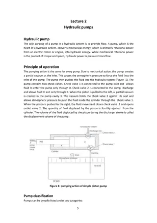
Hydraulic Symbols Basic Hydraulics HYDR 1305 For system diagrams and component identification
Flow Lines and Connections Main line Single Pilot line Four way junction Enclosure Hydraulic components in box or cabinet Flexible line Hose usually connecting parts with relative movement Reservoir Junction Single Junction Four way junction Crossing not connected
Functional Elements Triangle Direction of fluid flow Spring Tee Closed path or port Long sloping arrow that crosses another line indicates adjustability Arrow Straight or sloping path and flow direction Arrows
Equipment Accumulator Filter Solenoid Operator Shown Operator Pressure Gauge
Equipment Electric Motor M Pump Hydraulic motor Isolating valve
Equipment Check valve Flow in one direction FLOW RESTRICTED FLOW RESTRICTED FLOW One way flow control valve FREE FLOW FREE FLOW Adjustable Flow control valve Non-adjustable
Actuators Single acting spring return cylinder Single acting load return cylinder Double acting cylinder Rotary actuator
Pressure Regulators A pressure regulator symbol represents a normal state with the spring holding the regulator valve open. The dotted line represents the feedback, that opposes the spring and can vary the flow through the valve from full flow through shut off. Non-Adjustable regulator Adjustable regulator
Pressure Relief Valves A pressure relief valve symbol represents a normal state with the spring holding the valve closed The dotted line represents feed-forward, this opposes the spring and can lift the valve to allow flow. Non-adjustable relief valve Adjustable relief valve
Control Valve Symbols - Structure Boxes are used to indicate the number of valve positions. The number of adjacent boxes indicate whether a valve is a two position or three position valve. The boxes are two states of the same valve TWO POSITION VALVE THREE POSITION VALVE 1 2 1 2 3 Arrows are used to indicate the direction of flow. A tee indicates that a port is blocked (no flow). NO FLOW POSITION FLOW POSITION
Control Valve Symbols - Structure The function of a valve may be given by a pair of numerals separated by a stroke. Examples: 2/2, 3/2, 5/2, etc. The first numeral indicates the number of main ports. These are inlets and outlets. The second numeral indicates the number of physical positions the valve can be placed in. Such as left or right, pushed in or pulled out for two positions, and left / center / right for three position. A 3/2 valve therefore has 3 ports (normally these are inlet, outlet, and exhaust) and 2 states (the normal state and the operated state. 2/2 2 PORTS 2 POSITIONS 3/2 3 PORTS 2 POSITIONS
Control Valve Symbols - Structure The port connections are shown on only one of the boxes to indicate the shelf state. The shelf state is the state that the valve would be in if it were setting on the shelf with no fluid flow, not being operated, not powered, etc. Below, shown in the shelf state; flow is from port 1 to port 2 and port 3 is blocked. If the control valve is made to change state, the blocks are swapped. Flow is now from port 3 to 1 and now 2 is blocked. 1 OPERATED STATE FLOW P TO 1 E IS BLOCKED SHELF STATE FLOW 1 TO E P IS BLOCKED 2 3
Control Valve Symbols - Structure The control valve operator is shown against the box that the valve will change state to when operated. This is a push button symbol: The "shelf state" (in this case caused by a spring) is shown on the opposite box. If there is no spring than the control valve is operated by pushing the button in and pulling the button out. 1 1 2 3 2 3 SHOWN IN SHELF STATE (WITH SPRING) PUSH BUTTON IN GOES TO LEFT BLOCK STATE PUSH BUTTON RELEASED GOES BACK TO SHELF STATE AS SHOWN THERE IS NO SHELF STATE (NO SPRING) PUSH BUTTON PULLED AND PUSHED IN CHANGES STATES RESPECTIVELY NOTE ON DIAGRAM INDICATES IF PUSHED IN OR OUT FOR POSITION SHOWN.
Control Valve Symbols - Structure The valve symbol can be visualised as moving from one state to another state with the port connections not moving. The 3/2 control valve shown is frequently used for a single acting cylinder. 2 3 3/2 CONTROL VALVE SHOWN IN ITS TWO POSITIONS 2 3
1 E 2 P 3
1 E 2 P 3
1 E 2 P 3
1 E 2 P 3
1 E 2 P 3
Control Valve Symbols - Structure A 4/2 valve symbol is shown below. This valve could be used to operate two different pieces of equipment at the same time from the same control valve. 1 2 3 4
Control Valve Symbols - Structure A 5/2 valve symbol is shown below. The most frequent application is controlling a double acting cylinder. 1 2 SHELF STATE 4 5 3 1 2 OPERATED STATE 4 5 3
Control Valve Symbols - Structure 5/3 control valves have a normal central position that is set by springs or with a manual control such as a lever. The flow pattern in the center position varies with the type. Depending on the application, there are three types that may be used. 5/3 VALVE 1 2 4 5 3 LEVER OPERATED - SHOWN IN CENTER POSITION, ROCKS BACK AND FORTH SOLENOID OPERATED IF THE LEFT SOLENOID IS ENERGIZED, THE BOX NEXT TO IT WILL BE THE POSITION OF THE VALVE
Control Valve Symbols - Structure All valves types shown in the Shelf State Position Type 1. Type 2. Type 3.
Control Valve Symbols - Structure All valves types shown in the Left State Position Type 1. Type 2. Type 3.
Control Valve Symbols - Structure All valves types shown in the Shelf State Position Type 1. Type 2. Type 3.
Control Valve Symbols - Structure All valves types shown in the Right State Position Type 1. Type 2. Type 3.
Valve Operators Manual General manual Lever Push button Pedal Pull button Treadle Push/pull button Rotary knob
Control Valve Symbols - Operators Mechanical Plunger Pressure Spring normally as a return Pilot pressure Roller Differential pressure Uni-direction or one way trip Detent in 3 positions Electrical Solenoid direct Solenoid pilot