Understanding Hydraulic Actuators: Types and Applications


مامصلا لمع حرش ةقيرط
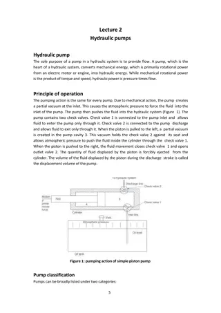
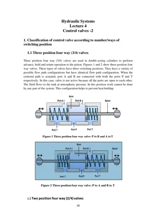
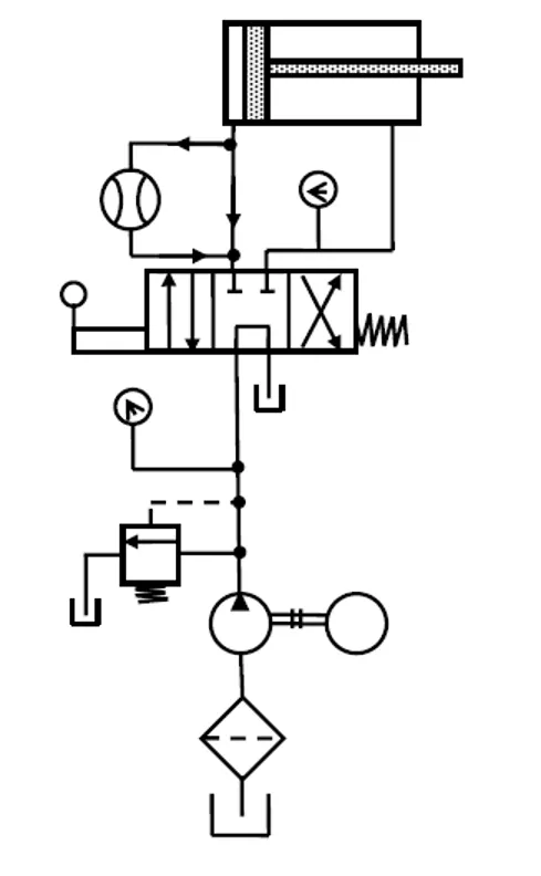
Figure 1.2
Control of a double-acting cylinder.
The circuit diagram to control double-acting cylinder is shown in Fig. 1.2. The control of a
double-acting hydraulic cylinder is described as follows:
1. When the 4/3 valve is in its neutral position (tandem design), the cylinder is hydraulically
locked, and the pump is unloaded back to the tank.
2. When the 4/3 valve is actuated into the flow path, the cylinder is extended against its load
as oil flows from port
P
through port
A
. Oil in the rod end of the cylinder is free to flow back
to the tank through the four-way valve from port B through port
T
.
3. When the 4/3 valve is actuated into the right-envelope configuration, the cylinder retracts
as oil flows from port
P
through port
B
. Oil in the blank end is returned to the tank via the
flow path from port
A
to port
T
.
At the ends of the stroke, there is no system demand for oil. Thus, the pump flow goes through
the relief valve at its pressure level setting unless the four-way valve is deactivated.
1
HYDRAULIC ACTUATORS
7.1 Introduction
Hydraulic systems are used to control and transmit power. A pump driven by a prime mover
such as an electric motor creates a flow of fluid, in which the pressure, direction and rate of
flow are controlled by valves. An actuator is used to convert the energy of fluid back into the
mechanical power. The amount of output power developed depends upon the flow rate, the
pressure drop across the actuator and its overall efficiency. Thus, hydraulic actuators are
devices used to convert pressure energy of the fluid into mechanical energy.
Depending on the type of actuation, hydraulic actuators are classified as follows:
1. Linear actuator: For linear actuation (hydraulic cylinders).
2. Rotary actuator: For rotary actuation (hydraulic motor).
3. Semi-rotary actuator: For limited angle of actuation (semi-rotary actuator).
Hydraulic linear actuators, as their name implies, provide motion in a straight line. The total
movement is a finite amount determined by the construction of the unit. They are usually
referred to as cylinders, rams and jacks. All these items are synonymous in general use,
although ram is sometimes intended to mean a single-acting cylinder and jack often refers to a
cylinder used for lifting. The function of hydraulic cylinder is to convert hydraulic power into
linear mechanical force or motion. Hydraulic cylinders extend and retract a piston rod to
provide a push or pull force to drive the external load along a straight -line path. Continuous
angular movement is achieved by rotary actuators, more generally known as a hydraulic motor.
Semi-rotary actuators are capable of limited angular movements that can be several complete
revolutions but 360 or less is more usual.
o
7.2 Types of Hydraulic Cylinders
Hydraulic cylinders are of the following types:
•
Single-acting cylinders.
•
Double-acting cylinders.
•
Telescopic cylinders.
•
Tandem cylinders.
2
7.2.1 Single-Acting Cylinders
A single-acting cylinder is simplest in design and is shown schematically in Fig.7.1. It consists
of a piston inside a cylindrical housing called barrel. On one end of the piston there is a rod,
which can reciprocate
.
At the opposite end, there is a port for the entrance and exit of oil.
Single-acting cylinders produce force in one direction by hydraulic pressure acting on the
piston. (Single-acting cylinders can exert a force in the extending direction only.) The return
of the piston is not done hydraulically. In single-acting cylinders, retraction is done either by
gravity or by a spring.
Figure 7.1
Single-acting cylinders
According to the type of return, single-acting cylinders are classified as follows:
•
Gravity-return single-acting cylinder.
•
Spring-return single-acting cylinder.
7.2.1.1 Gravity-Return Single-Acting Cylinder
Figure 7.2
Gravity-return single-acting cylinder: (a) Push type; (b) pull type
3
Figure7.2 shows gravity-return-type single-acting cylinders. In the push type [Fig. 7.2(a)], the
cylinder extends to lift a weight against the force of gravity by applying oil pressure at the
blank end. The oil is passed through the blank-end port or pressure port. The rod-end port or
vent port is open to atmosphere so that air can flow freely in and out of the rod end of the
cylinder. To retract the cylinder, the pressure is simply removed from the piston by connecting
the pressure port to the tank. This allows the weight of the load to push the fluid out of the
cylinder back to the tank. In pull-type gravity-return-type single-acting cylinder, the cylinder
[Fig. 7.2(b)] lifts the weight by retracting. The blank-end port is the pressure port and blind-
end port is now the vent port. This cylinder automatically extends whenever the pressure port
is connected to the tank.
7.2.1.2 Spring-Return Single-Acting Cylinder
A spring-return single-acting cylinder is shown in Fig.7.3. In push type [Fig. 7.3(a)], the
pressure is sent through the pressure port situated at the blank end of the cylinder. When the
pressure is released, the spring automatically returns the cylinder to the fully retracted position.
The vent port is open to atmosphere so that air can flow freely in and out of the rod end of the
cylinder.
Figure 7.3(b) shows a spring-return single-acting cylinder. In this design, the cylinder retracts
when the pressure port is connected to the pump flow and extends whenever the pressure port
is connected to the tank. Here the pressure port is situated at the rod end of the cylinder.
Figure 7.3
(a) Push- and (b) pull-type single-acting cylinders
7.2.2 Double-Acting Cylinder
There are two types of double-acting cylinders:
•
Double-acting cylinder with a piston rod on one side.
•
Double-acting cylinder with a piston rod on both sides.
4
7.2.2.1 Double-Acting Cylinder with a Piston Rod on One Side
Figure 7.4 shows the operation of a double-acting cylinder with a piston rod on one side. To
extend the cylinder, the pump flow is sent to the blank-end port as in Fig. 7.4(a). The fluid from
the rod-end port returns to the reservoir. To retract the cylinder, the pump flow is sent to the
rod-end port and the fluid from the blank-end port returns to the tank as in Fig.7.4(b).
Figure 7.4
Double-acting cylinder with a piston rod on one side
7.2.2.2
Double-Acting
Cylinder
with
a
Piston
Rod
on
Both
Sides
Figure 7.5
Double-acting cylinder with a piston rod on one side
5
A double-acting cylinder with a piston rod on both sides (Fig.7.5) is a cylinder with a rod
extending from both ends. This cylinder can be used in an application where work can be done
by both ends of the cylinder, thereby making the cylinder more productive. Double-rod
cylinders can withstand higher side loads because they have an extra bearing, one on each rod,
to withstand the loading.
7.2.3 Telescopic Cylinder
A telescopic cylinder (shown in Fig. 7.6) is used when a long stroke length and a short-retracted
length are required. The telescopic cylinder extends in stages, each stage consisting of a sleeve
that fits inside the previous stage. One application for this type of cylinder is raising a dump
truck bed. Telescopic cylinders are available in both single-acting and double-acting models.
They are more expensive than standard cylinders due to their more complex construction.
They generally consist of a nest of tubes and operate on the displacement principle. The tubes
are supported by bearing rings, the innermost (rear) set of which have grooves or channels to
allow fluid flow. The front bearing assembly on each section includes seals and wiper rings.
Stop rings limit the movement of each section, thus preventing separation. When the cylinder
extends, all the sections move together until the outer section is prevented from further
extension by its stop ring. The remaining sections continue out-stroking until the second
outermost section reaches the limit of its stroke; this process continues until all sections are
extended, the innermost one being the last of all.
Figure 7.6
Telescopic cylinder
For a given input flow rate, the speed of operation increases in steps as each successive section
reaches the end of its stroke. Similarly, for a specific pressure, the load-lifting capacity
decreases for each successive section
6
7.2.4 Tandem Cylinder
Figure 7.7:
Tandem cylinder
A tandem cylinder, shown in Fig. 7.7, is used in applications where a large amount of force is
required from a small-diameter cylinder. Pressure is applied to both pistons, resulting in
increased force because of the larger area. The drawback is that these cylinders must be longer
than a standard cylinder to achieve an equal speed because flow must go to both pistons.
7.2.4.1 Through-Rod Cylinders
These are similar in construction to the standard double-acting cylinders, but have a cylinder
rod extending through both cylinder end caps. Although it is possible to have both the piston
rods with different diameters at each end of the cylinder, generally the rods have the same
diameters. The main applications of through-rod cylinders are as follows: the same speed is
required in both the directions, both ends of the rod can be utilized to do work and the non-
working end is used to indicate or signal the position of the load. In some applications, the rod
is fixed at both the ends and the cylinder body carrying the load moves on the rod.
A major problem in the manufacture of through-rod cylinders is achieving the correct
alignment and concentricity of cylinder bore, piston, end caps and rods. Any misalignment can
result in excessive seal wear and premature cylinder failure.
7.2.4.2 Displacement Cylinders
A displacement-type hydraulic cylinder shown in Fig. 7.8 consists of a rod that is displaced
from inside a tube by pumping hydraulic fluid into the tube. The volume of the rod leaving the
tube is equal to the volume of fluid entering the tube, hence the name “displacement cylinder.”
The rod of the displacement cylinder is guided by bearings in the nose or neck of the cylinder
body. A collar on the end of the rod prevents it from being ejected and limits the stroke of the
cylinder. Elastomer seals in the neck prevent any leakage of fluid along the outside of the rod.
This design is a single-acting “push” or extension cylinder, which has to be retracted by gravity,
7
a spring or some external force. The bore of the cylinder body does not require machining other
than that for the neck bearing and the inlet port; the manufacturing cost is, therefore, low when
compared with other types or hydraulic cylinders.
The maximum thrust exerted by a displacement cylinder is given by Maximum
Figure 7.8:
Displacement cylinders
Example 7.1
A displacement-type cylinder has a rod of 65 mm diameter and is powered by a hand pump
with a displacement of 5 mL per double stroke. The maximum operating pressure of the system
is to be limited to 350 bar. (a) Draw a suitable circuit diagram showing the cylinder, pump and
any additional valving required. (b) Calculate the number of double pumping strokes needed
to extend the cylinder rod by 50 mm. (c) Calculate the maximum load that could be raised using
this system.
Solution:
(a)
The circuit diagram is given in Fig. 7.9.
9
Example 7.2
A three-stage displacement-type telescopic cylinder is used to tilt the body of a lorry (Fig.
7.10). When the lorry is fully laden, the cylinder has to exert a force equivalent to 4000 kg at
all points in its stroke. The outside diameters of the tubes forming the three stages are 60, 80
and 100 mm. If the pump powering the cylinder delivers 10 LPM, calculate the extend speed
and pressure required for each stage of the cylinder when tilting a fully laden lorry.
10
Figure 7.10
Telescopic cylinders are made in a standard range for vehicle applications. Although
non-standard cylinders can be obtained, they tend to be very expensive if ordered as a
single piece.
7.3 Standard Metric Cylinders
Table 7.1 gives preferred sizes for the cylinder bore and rod diameter of metric cylinders.
Most cylinder manufacturers have based their standard range of metric cylinders on these
recommendations, offering two rod sizes for each cylinder bore.
A number of combinations have a piston rod to piston diameter ratio in the region of 0.7,
which gives an annulus area of approximately one-half of the full-bore area. This area ratio
is of use in regenerative circuits to give similar values of speed and thrust on both the
extension and retraction strokes. Table 7.2 gives the graphical symbols for various kinds of
cylinders.
Table 7.1
Recommended cylinder bore and rod sizes
11
Table 7.2
Graphical symbols of different linear actuators
7.4 Cylinder Force, Velocity and Power
The output force (
F
) and piston velocity (
v
) of double-acting cylinders are not the same for
extension and retraction strokes.
12
Figure 7.11:
Effective area during (a) extension strokes and (b)retraction strokes
During the extension stroke shown in Fig.7.11(a), the fluid pressure acts on the entire circular
piston area
A
p. During the retraction stroke, the fluid enters the rod-end side and the fluid
pressure acts on the smaller
annular area between the rod and cylinder bore (
A
p−
A
r) as shown
by the shaded area in Fig.7.11(b) (
A
r is the area of the piston rod). Due to the difference in the
cross-sectional area, the velocity of the piston changes. Because
A
p is greater than (
A
p−
A
r), the
retraction velocity (
v
ret) is greater than the extension velocity (
v
ext) for the same flow rate.
During the extension stroke, the fluid pressure acts on the entire piston area (
A
r), while during
the retraction stroke, the fluid pressure acts on the annular area (
A
p−
A
r). This difference in area
accounts for the difference in output forces during extension and retraction strokes. Because
A
r
is greater than (
A
p−
A
r), the extension force is greater than the retraction force for the same
operating pressure.
Force and velocity during extension stroke
13
7.5 Acceleration and Deceleration of Cylinder Loads
Cylinders are subjected to acceleration and deceleration during their operation. Cylinders
are decelerated to provide cushioning and cylinders are accelerated to reduce the cycle
time of the operation.
7.5.1 Acceleration
To calculate the acceleration of cylinder loads, the equations of motion must be understood.
Let
u
be the initial velocity,
v
the velocity after a time
t
,
s
the distance moved during the time
t
and
a
the acceleration during the time
t
. The standard equations of motion are as follows
v
=
u+ at
v
=
u
+ 2
as
2
2
s
=
u.t
+1/2
at
2
s
=1/2(
u
+
v
)
t
The force
F
to accelerate a weight
W
horizontally with an acceleration
a
is given by
Force = Mass × Acceleration
F
= W / g
where
g
is the acceleration due to gravity and is 9.81 m/s . The force
P
required to
overcome friction is given by
P
=
µW
, where
µ
is the coefficient of friction.
2
Note: Dynamic cylinder thrust
In dynamic applications, the load inertia, seal friction, load friction, etc., must be allowed
for calculating the dynamic thrust. As a first approximation, the dynamic thrust can be
14
taken as 0.9 times the static thrust. Cylinder seal friction varies with seal and cylinder
design. The pressure required to overcome seal friction is not readily available from the
majority of cylinder manufacturers. The seal friction breakout pressure can be taken as 5
bar for calculation purposes. It reduces when the piston starts to move. The pressure
required to overcome seal friction reduces as the cylinder bore size increases and varies
according to the seal design.
Example 7.3
A cylinder is required to move a 10 kN load 150 mm in 0.5 s. What is the output power?
Example 7.4
A cylinder is required to extend at a minimum speed of 0.75 m/s in a system with a flow
rate of 60 LPM. What cylinder size is required?
Example 7.5
An 8 cm diameter hydraulic cylinder has a 4 cm diameter rod. If the cylinder receives flow
at 100 LPM and 12 MPa, find the (a) extension and retraction speeds and (b) extension
and retraction load carrying capacities.
15
Example 7.6
A pump supplies oil at 0.0016 m /s to a 40 mm diameter double-acting hydraulic cylinder.
If the load is 5000 N (extending and retracting) and the rod diameter is 20 mm, find the
(a) Hydraulic pressure during the extending stroke.
(b) Piston velocity during the extending stroke.
3
(c) Cylinder kW power during the extending stroke.
(d) Hydraulic pressure during the retracting stroke,
(e) Piston velocity during the retracting stroke.
(f) Cylinder kW power during the retracting stroke.
16
Example 7.7
A hydraulic cylinder has a rod diameter equal to one half the piston diameter. Determine
the difference in load-carrying capacity between extension and retraction stroke if pressure
is constant. What would happen if the pressure were applied to both sides of the cylinder
at the same time?
Solution:
Forward or extending stroke is
F
ext =
p
x
Ap
17
Example 7.8
A cylinder with a bore of 150 mm and a piston rod diameter of 105 mm, has to extend
with a speed of 7 m/s, pressure applied is 150 bar. Calculate
(a) The flow rate in LPM of oil to extend the cylinder
(b) The flow rate in LPM from annulus side to extend the cylinder.
(c) The retract speed in m/min using (a).
(d) The flow rate from full bore end on retract.
18
7.6 Various Methods of Applying Linear Motion Using Hydraulic
Cylinders
A cylinder must produce a force equal to the load the cylinder is required to overcome. A
cylinder may be placed with its axis vertical, horizontal or inclined depending on the load
to be actuated.
1. Vertical cylinder:
In a vertical cylinder, the load to be actuated is in the vertical
direction as shown in Fig. 7.12. Then the cylinder load
F
is equal to the weight
W
of the object, acting in the vertical direction.
Figure 7.12
Cylinder load– vertical cylinder
2. Horizontal cylinder:
The schematic diagram of horizontal cylinder is shown in Fig.
7.13. Ina horizontal cylinder, the cylinder load is theoretically zero, because no
component of the object’s weight acts along the axis of the cylinder. However,
when the object slides across the horizontal surface, the cylinder must overcome
the frictional force created between the object and the horizontal surface.
19
Figure 7.13
Cylinder load –horizontal cylinder
3. Inclined cylinder:
In an inclined cylinder as shown in Fig. 7.14, the cylinder load
equals the component of the object’s weight acting along the axis of the cylinder
and frictional force
Figure 7.14
Cylinder load –inclined cylinder
For an inclined cylinder, the load the cylinder must overcome is less than the weight of
the object to be moved if the object does not slide on an inclined surface. The cylinder
loads calculated as above are based on moving an object at a constant velocity. But when
the object has to be accelerated from zero velocity to a steady-state velocity, an additional
force called inertia force must be added to the weight component and any frictional force
involved.
Let
F
load =
W
= weight or load acting vertically downward,
F
cyl = load acting on the cylinder,
F
bear = force on the bearings and
α= angle between the load
W
and the axis of the cylinder.
Then,
F
cyl =
F
loadcos(
α
)
F
bear =
F
loadsin(
α
)
20
Example 7.9
Find the cylinder force required to move a 6000 N weight along a horizontal surface at a
constant velocity (Fig. 7.15). The coefficient of friction between the weight and horizontal
support surface is 0.14.
Figure 7.15
Example 7.10
Find the cylinder force required to lift a 6000 N weight along a direction that is 30° from
the horizontal direction as shown in Fig. 7.16. The weight is moved at a constant velocity.
Figure 7.16
21
Example 7.11
A 6000 N weight is to be lifted upward in a vertical direction for the system shown in Fig.
7.17. Find the cylinder force required to
(a) Move the weight at a constant velocity of 1.75 m/s.
(b) Accelerate the weight from zero velocity to 1.75 m/s in 0.5 s.
Load
= Cylinder force
Figure 7.17
Example 7.12
A 10000 N weight is to be lowered by a vertical cylinder as shown in Fig. 7.18. The
cylinder has a 75 mm diameter piston and 50 mm diameter rod. The weight is to decelerate
from 100 m/min to a stop in 0.5 s. Determine the required pressure in the rod end of the
cylinder during the deceleration motion.
22
Figure 7.18
Example 7.13
A 27000 N weight is being pushed up on an inclined surface at a constant speed by a
cylinder, as shown in Fig. 7.19. The coefficient of friction between the weight and the
inclined surface equals 0.15.
(a) Determine the required cylinder piston diameter for the pressure of 6894 kPa,
(b) Determine the required cylinder piston diameter, if the weight is to accelerate from a 0
mm/s to a 1524 mm/s in 0.5 s.
10000 N
23
Figure 7.19
24
Example 7.14
A hydraulic cylinder has a bore of 200 mm and a piston rod diameter of 140 mm. For an
extend speed of 5 m/min, calculate
(a) The supply flow rate.
(b) The flow rate from the annulus side on extend. (c) The
retract speed using
Q
E.
(d) The flow rate from the full bore end on retract.
Also, if the maximum pressure applied to the cylinder is 100 bar, calculate the (e)
dynamic extend thrust and the (f) dynamic retract thrust assuming that dynamic thrust
= 0.9 X static thrust.
Moreover, the hydraulic cylinder having a bore of 200 mm diameter and a rod of 140
mm diameter are connected regeneratively. (g) If the same flow rate of 157 L/min is
used, calculate the extend speed. (h) If the maximum system pressure is 100 bar,
calculate the dynamic extend thrust.
25
Example 7.15
A mass of 2000 kg is to be accelerated horizontally up to a velocity of 1 m/s from the rest
over a distance of 50 mm (Fig. 7.20). The coefficient of friction between the load and
guide is 0.15. Calculate the bore of the cylinder required to accelerate this load if the
maximum allowable pressure at the full bore end is 100 bar (take seal friction to be
equivalent to a pressure drop of 5 bar). Assume that the back pressure at the annulus end
of the cylinder is zero.
26
Figure 7.20
Hydraulic actuators play a crucial role in converting hydraulic energy into mechanical power in various systems. This article discusses the types of hydraulic actuators, focusing on hydraulic cylinders and their operation principles. It covers single-acting and double-acting cylinders, highlighting their design and functionality. The control of a double-acting cylinder is explained in detail, along with the different types of hydraulic cylinders such as telescopic and tandem cylinders. Additionally, the classification of hydraulic actuators based on linear, rotary, and semi-rotary actuation is explored, providing insights into their applications and significance in power transmission systems.

Download Presentation

Please find below an Image/Link to download the presentation.
The content on the website is provided AS IS for your information and personal use only. It may not be sold, licensed, or shared on other websites without obtaining consent from the author. Download presentation by click this link. If you encounter any issues during the download, it is possible that the publisher has removed the file from their server.
E N D
Presentation Transcript
Figure 1.2 Control of a double-acting cylinder. The circuit diagram to control double-acting cylinder is shown in Fig. 1.2. The control of a double-acting hydraulic cylinder is described as follows: 1. When the 4/3 valve is in its neutral position (tandem design), the cylinder is hydraulically locked, and the pump is unloaded back to the tank. 2. When the 4/3 valve is actuated into the flow path, the cylinder is extended against its load as oil flows from port P through port A. Oil in the rod end of the cylinder is free to flow back to the tank through the four-way valve from port B through port T. 3. When the 4/3 valve is actuated into the right-envelope configuration, the cylinder retracts as oil flows from port P through port B. Oil in the blank end is returned to the tank via the flow path from port A to port T. At the ends of the stroke, there is no system demand for oil. Thus, the pump flow goes through the relief valve at its pressure level setting unless the four-way valve is deactivated.
1 HYDRAULIC ACTUATORS 7.1 Introduction Hydraulic systems are used to control and transmit power. A pump driven by a prime mover such as an electric motor creates a flow of fluid, in which the pressure, direction and rate of flow are controlled by valves. An actuator is used to convert the energy of fluid back into the mechanical power. The amount of output power developed depends upon the flow rate, the pressure drop across the actuator and its overall efficiency. Thus, hydraulic actuators are devices used to convert pressure energy of the fluid into mechanical energy. Depending on the type of actuation, hydraulic actuators are classified as follows: 1. Linear actuator: For linear actuation (hydraulic cylinders). 2. Rotary actuator: For rotary actuation (hydraulic motor). 3. Semi-rotary actuator: For limited angle of actuation (semi-rotary actuator). Hydraulic linear actuators, as their name implies, provide motion in a straight line. The total movement is a finite amount determined by the construction of the unit. They are usually referred to as cylinders, rams and jacks. All these items are synonymous in general use, although ram is sometimes intended to mean a single-acting cylinder and jack often refers to a cylinder used for lifting. The function of hydraulic cylinder is to convert hydraulic power into linear mechanical force or motion. Hydraulic cylinders extend and retract a piston rod to provide a push or pull force to drive the external load along a straight -line path. Continuous angular movement is achieved by rotary actuators, more generally known as a hydraulic motor. Semi-rotary actuators are capable of limited angular movements that can be several complete revolutions but 360 or less is more usual. o 7.2 Types of Hydraulic Cylinders Hydraulic cylinders are of the following types: Single-acting cylinders. Double-acting cylinders. Telescopic cylinders. Tandem cylinders.
2 7.2.1 Single-Acting Cylinders A single-acting cylinder is simplest in design and is shown schematically in Fig.7.1. It consists of a piston inside a cylindrical housing called barrel. On one end of the piston there is a rod, which can reciprocate. At the opposite end, there is a port for the entrance and exit of oil. Single-acting cylinders produce force in one direction by hydraulic pressure acting on the piston. (Single-acting cylinders can exert a force in the extending direction only.) The return of the piston is not done hydraulically. In single-acting cylinders, retraction is done either by gravity or by a spring. Figure 7.1 Single-acting cylinders According to the type of return, single-acting cylinders are classified as follows: Gravity-return single-acting cylinder. Spring-return single-acting cylinder. 7.2.1.1 Gravity-Return Single-Acting Cylinder Figure 7.2 Gravity-return single-acting cylinder: (a) Push type; (b) pull type
3 Figure7.2 shows gravity-return-type single-acting cylinders. In the push type [Fig. 7.2(a)], the cylinder extends to lift a weight against the force of gravity by applying oil pressure at the blank end. The oil is passed through the blank-end port or pressure port. The rod-end port or vent port is open to atmosphere so that air can flow freely in and out of the rod end of the cylinder. To retract the cylinder, the pressure is simply removed from the piston by connecting the pressure port to the tank. This allows the weight of the load to push the fluid out of the cylinder back to the tank. In pull-type gravity-return-type single-acting cylinder, the cylinder [Fig. 7.2(b)] lifts the weight by retracting. The blank-end port is the pressure port and blind- end port is now the vent port. This cylinder automatically extends whenever the pressure port is connected to the tank. 7.2.1.2 Spring-Return Single-Acting Cylinder A spring-return single-acting cylinder is shown in Fig.7.3. In push type [Fig. 7.3(a)], the pressure is sent through the pressure port situated at the blank end of the cylinder. When the pressure is released, the spring automatically returns the cylinder to the fully retracted position. The vent port is open to atmosphere so that air can flow freely in and out of the rod end of the cylinder. Figure 7.3(b) shows a spring-return single-acting cylinder. In this design, the cylinder retracts when the pressure port is connected to the pump flow and extends whenever the pressure port is connected to the tank. Here the pressure port is situated at the rod end of the cylinder. Figure 7.3 (a) Push- and (b) pull-type single-acting cylinders 7.2.2 Double-Acting Cylinder There are two types of double-acting cylinders: Double-acting cylinder with a piston rod on one side. Double-acting cylinder with a piston rod on both sides.
4 7.2.2.1 Double-Acting Cylinder with a Piston Rod on One Side Figure 7.4 shows the operation of a double-acting cylinder with a piston rod on one side. To extend the cylinder, the pump flow is sent to the blank-end port as in Fig. 7.4(a). The fluid from the rod-end port returns to the reservoir. To retract the cylinder, the pump flow is sent to the rod-end port and the fluid from the blank-end port returns to the tank as in Fig.7.4(b). Figure 7.4 Double-acting cylinder with a piston rod on one side 7.2.2.2 Double-Acting Cylinder with a Piston Rod on Both Sides Figure 7.5 Double-acting cylinder with a piston rod on one side
5 A double-acting cylinder with a piston rod on both sides (Fig.7.5) is a cylinder with a rod extending from both ends. This cylinder can be used in an application where work can be done by both ends of the cylinder, thereby making the cylinder more productive. Double-rod cylinders can withstand higher side loads because they have an extra bearing, one on each rod, to withstand the loading. 7.2.3 Telescopic Cylinder A telescopic cylinder (shown in Fig. 7.6) is used when a long stroke length and a short-retracted length are required. The telescopic cylinder extends in stages, each stage consisting of a sleeve that fits inside the previous stage. One application for this type of cylinder is raising a dump truck bed. Telescopic cylinders are available in both single-acting and double-acting models. They are more expensive than standard cylinders due to their more complex construction. They generally consist of a nest of tubes and operate on the displacement principle. The tubes are supported by bearing rings, the innermost (rear) set of which have grooves or channels to allow fluid flow. The front bearing assembly on each section includes seals and wiper rings. Stop rings limit the movement of each section, thus preventing separation. When the cylinder extends, all the sections move together until the outer section is prevented from further extension by its stop ring. The remaining sections continue out-stroking until the second outermost section reaches the limit of its stroke; this process continues until all sections are extended, the innermost one being the last of all. Figure 7.6 Telescopic cylinder For a given input flow rate, the speed of operation increases in steps as each successive section reaches the end of its stroke. Similarly, for a specific pressure, the load-lifting capacity decreases for each successive section
6 7.2.4 Tandem Cylinder Figure 7.7: Tandem cylinder A tandem cylinder, shown in Fig. 7.7, is used in applications where a large amount of force is required from a small-diameter cylinder. Pressure is applied to both pistons, resulting in increased force because of the larger area. The drawback is that these cylinders must be longer than a standard cylinder to achieve an equal speed because flow must go to both pistons. 7.2.4.1 Through-Rod Cylinders These are similar in construction to the standard double-acting cylinders, but have a cylinder rod extending through both cylinder end caps. Although it is possible to have both the piston rods with different diameters at each end of the cylinder, generally the rods have the same diameters. The main applications of through-rod cylinders are as follows: the same speed is required in both the directions, both ends of the rod can be utilized to do work and the non- working end is used to indicate or signal the position of the load. In some applications, the rod is fixed at both the ends and the cylinder body carrying the load moves on the rod. A major problem in the manufacture of through-rod cylinders is achieving the correct alignment and concentricity of cylinder bore, piston, end caps and rods. Any misalignment can result in excessive seal wear and premature cylinder failure. 7.2.4.2 Displacement Cylinders A displacement-type hydraulic cylinder shown in Fig. 7.8 consists of a rod that is displaced from inside a tube by pumping hydraulic fluid into the tube. The volume of the rod leaving the tube is equal to the volume of fluid entering the tube, hence the name displacement cylinder. The rod of the displacement cylinder is guided by bearings in the nose or neck of the cylinder body. A collar on the end of the rod prevents it from being ejected and limits the stroke of the cylinder. Elastomer seals in the neck prevent any leakage of fluid along the outside of the rod. This design is a single-acting push or extension cylinder, which has to be retracted by gravity,
7 a spring or some external force. The bore of the cylinder body does not require machining other than that for the neck bearing and the inlet port; the manufacturing cost is, therefore, low when compared with other types or hydraulic cylinders. The maximum thrust exerted by a displacement cylinder is given by Maximum Figure 7.8: Displacement cylinders Example 7.1 A displacement-type cylinder has a rod of 65 mm diameter and is powered by a hand pump with a displacement of 5 mL per double stroke. The maximum operating pressure of the system is to be limited to 350 bar. (a) Draw a suitable circuit diagram showing the cylinder, pump and any additional valving required. (b) Calculate the number of double pumping strokes needed to extend the cylinder rod by 50 mm. (c) Calculate the maximum load that could be raised using this system. Solution: (a) The circuit diagram is given in Fig. 7.9.
9 Example 7.2 A three-stage displacement-type telescopic cylinder is used to tilt the body of a lorry (Fig. 7.10). When the lorry is fully laden, the cylinder has to exert a force equivalent to 4000 kg at all points in its stroke. The outside diameters of the tubes forming the three stages are 60, 80 and 100 mm. If the pump powering the cylinder delivers 10 LPM, calculate the extend speed and pressure required for each stage of the cylinder when tilting a fully laden lorry.
10 Figure 7.10 Telescopic cylinders are made in a standard range for vehicle applications. Although non-standard cylinders can be obtained, they tend to be very expensive if ordered as a single piece. 7.3 Standard Metric Cylinders Table 7.1 gives preferred sizes for the cylinder bore and rod diameter of metric cylinders. Most cylinder manufacturers have based their standard range of metric cylinders on these recommendations, offering two rod sizes for each cylinder bore. A number of combinations have a piston rod to piston diameter ratio in the region of 0.7, which gives an annulus area of approximately one-half of the full-bore area. This area ratio is of use in regenerative circuits to give similar values of speed and thrust on both the extension and retraction strokes. Table 7.2 gives the graphical symbols for various kinds of cylinders. Table 7.1 Recommended cylinder bore and rod sizes
11 Table 7.2 Graphical symbols of different linear actuators 7.4 Cylinder Force, Velocity and Power The output force (F) and piston velocity (v) of double-acting cylinders are not the same for extension and retraction strokes.
12 Figure 7.11: Effective area during (a) extension strokes and (b)retraction strokes During the extension stroke shown in Fig.7.11(a), the fluid pressure acts on the entire circular piston area Ap. During the retraction stroke, the fluid enters the rod-end side and the fluid pressure acts on the smaller annular area between the rod and cylinder bore (Ap Ar) as shown by the shaded area in Fig.7.11(b) (Ar is the area of the piston rod). Due to the difference in the cross-sectional area, the velocity of the piston changes. Because Ap is greater than (Ap Ar), the retraction velocity (vret) is greater than the extension velocity (vext) for the same flow rate. During the extension stroke, the fluid pressure acts on the entire piston area (Ar), while during the retraction stroke, the fluid pressure acts on the annular area (Ap Ar). This difference in area accounts for the difference in output forces during extension and retraction strokes. Because Ar is greater than (Ap Ar), the extension force is greater than the retraction force for the same operating pressure. Force and velocity during extension stroke
13 7.5 Acceleration and Deceleration of Cylinder Loads Cylinders are subjected to acceleration and deceleration during their operation. Cylinders are decelerated to provide cushioning and cylinders are accelerated to reduce the cycle time of the operation. 7.5.1 Acceleration To calculate the acceleration of cylinder loads, the equations of motion must be understood. Let u be the initial velocity, v the velocity after a time t,s the distance moved during the time t and a the acceleration during the time t. The standard equations of motion are as follows v = u+ at v = u + 2as 2 2 s =u.t +1/2 at 2 s =1/2(u + v ) t The force F to accelerate a weight W horizontally with an acceleration a is given by Force = Mass Acceleration F = W / g 2 where g is the acceleration due to gravity and is 9.81 m/s . The force P required to overcome friction is given by P = W, where is the coefficient of friction. Note: Dynamic cylinder thrust In dynamic applications, the load inertia, seal friction, load friction, etc., must be allowed for calculating the dynamic thrust. As a first approximation, the dynamic thrust can be
14 taken as 0.9 times the static thrust. Cylinder seal friction varies with seal and cylinder design. The pressure required to overcome seal friction is not readily available from the majority of cylinder manufacturers. The seal friction breakout pressure can be taken as 5 bar for calculation purposes. It reduces when the piston starts to move. The pressure required to overcome seal friction reduces as the cylinder bore size increases and varies according to the seal design. Example 7.3 A cylinder is required to move a 10 kN load 150 mm in 0.5 s. What is the output power? Example 7.4 A cylinder is required to extend at a minimum speed of 0.75 m/s in a system with a flow rate of 60 LPM. What cylinder size is required? Example 7.5 An 8 cm diameter hydraulic cylinder has a 4 cm diameter rod. If the cylinder receives flow at 100 LPM and 12 MPa, find the (a) extension and retraction speeds and (b) extension and retraction load carrying capacities.
15 Example 7.6 A pump supplies oil at 0.0016 m /s to a 40 mm diameter double-acting hydraulic cylinder. If the load is 5000 N (extending and retracting) and the rod diameter is 20 mm, find the (a) Hydraulic pressure during the extending stroke. (b) Piston velocity during the extending stroke. 3 (c) Cylinder kW power during the extending stroke. (d) Hydraulic pressure during the retracting stroke, (e) Piston velocity during the retracting stroke. (f) Cylinder kW power during the retracting stroke.
16 Example 7.7 A hydraulic cylinder has a rod diameter equal to one half the piston diameter. Determine the difference in load-carrying capacity between extension and retraction stroke if pressure is constant. What would happen if the pressure were applied to both sides of the cylinder at the same time? Solution: Forward or extending stroke is Fext = p x Ap
17 Example 7.8 A cylinder with a bore of 150 mm and a piston rod diameter of 105 mm, has to extend with a speed of 7 m/s, pressure applied is 150 bar. Calculate (a) The flow rate in LPM of oil to extend the cylinder (b) The flow rate in LPM from annulus side to extend the cylinder. (c) The retract speed in m/min using (a). (d) The flow rate from full bore end on retract.
18 7.6 Various Methods of Applying Linear Motion Using Hydraulic Cylinders A cylinder must produce a force equal to the load the cylinder is required to overcome. A cylinder may be placed with its axis vertical, horizontal or inclined depending on the load to be actuated. 1. Vertical cylinder: In a vertical cylinder, the load to be actuated is in the vertical direction as shown in Fig. 7.12. Then the cylinder load F is equal to the weight W of the object, acting in the vertical direction. Figure 7.12 Cylinder load vertical cylinder 2. Horizontal cylinder: The schematic diagram of horizontal cylinder is shown in Fig. 7.13. Ina horizontal cylinder, the cylinder load is theoretically zero, because no component of the object s weight acts along the axis of the cylinder. However, when the object slides across the horizontal surface, the cylinder must overcome the frictional force created between the object and the horizontal surface.
19 Figure 7.13 Cylinder load horizontal cylinder 3. Inclined cylinder: In an inclined cylinder as shown in Fig. 7.14, the cylinder load equals the component of the object s weight acting along the axis of the cylinder and frictional force Figure 7.14 Cylinder load inclined cylinder For an inclined cylinder, the load the cylinder must overcome is less than the weight of the object to be moved if the object does not slide on an inclined surface. The cylinder loads calculated as above are based on moving an object at a constant velocity. But when the object has to be accelerated from zero velocity to a steady-state velocity, an additional force called inertia force must be added to the weight component and any frictional force involved. Let Fload = W = weight or load acting vertically downward, Fcyl = load acting on the cylinder, Fbear = force on the bearings and = angle between the load W and the axis of the cylinder. Then, Fcyl = Floadcos( ) Fbear = Floadsin( )
20 Example 7.9 Find the cylinder force required to move a 6000 N weight along a horizontal surface at a constant velocity (Fig. 7.15). The coefficient of friction between the weight and horizontal support surface is 0.14. Figure 7.15 Example 7.10 Find the cylinder force required to lift a 6000 N weight along a direction that is 30 from the horizontal direction as shown in Fig. 7.16. The weight is moved at a constant velocity. Figure 7.16
21 Example 7.11 A 6000 N weight is to be lifted upward in a vertical direction for the system shown in Fig. 7.17. Find the cylinder force required to (a) Move the weight at a constant velocity of 1.75 m/s. (b) Accelerate the weight from zero velocity to 1.75 m/s in 0.5 s. Load = Cylinder force Figure 7.17 Example 7.12 A 10000 N weight is to be lowered by a vertical cylinder as shown in Fig. 7.18. The cylinder has a 75 mm diameter piston and 50 mm diameter rod. The weight is to decelerate from 100 m/min to a stop in 0.5 s. Determine the required pressure in the rod end of the cylinder during the deceleration motion.
22 10000 N Figure 7.18 Example 7.13 A 27000 N weight is being pushed up on an inclined surface at a constant speed by a cylinder, as shown in Fig. 7.19. The coefficient of friction between the weight and the inclined surface equals 0.15. (a) Determine the required cylinder piston diameter for the pressure of 6894 kPa, (b) Determine the required cylinder piston diameter, if the weight is to accelerate from a 0 mm/s to a 1524 mm/s in 0.5 s.
23 Figure 7.19
24 Example 7.14 A hydraulic cylinder has a bore of 200 mm and a piston rod diameter of 140 mm. For an extend speed of 5 m/min, calculate (a) The supply flow rate. (b) The flow rate from the annulus side on extend. (c) The retract speed using QE. (d) The flow rate from the full bore end on retract. Also, if the maximum pressure applied to the cylinder is 100 bar, calculate the (e) dynamic extend thrust and the (f) dynamic retract thrust assuming that dynamic thrust = 0.9 X static thrust. Moreover, the hydraulic cylinder having a bore of 200 mm diameter and a rod of 140 mm diameter are connected regeneratively. (g) If the same flow rate of 157 L/min is used, calculate the extend speed. (h) If the maximum system pressure is 100 bar, calculate the dynamic extend thrust.
25 Example 7.15 A mass of 2000 kg is to be accelerated horizontally up to a velocity of 1 m/s from the rest over a distance of 50 mm (Fig. 7.20). The coefficient of friction between the load and guide is 0.15. Calculate the bore of the cylinder required to accelerate this load if the maximum allowable pressure at the full bore end is 100 bar (take seal friction to be equivalent to a pressure drop of 5 bar). Assume that the back pressure at the annulus end of the cylinder is zero.
26 Figure 7.20