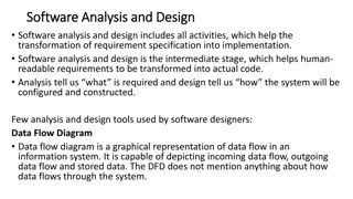
Understanding Software Architectural Design in Computer-Based Systems
Exploring the importance of software architectural design in computer-based systems, this content covers key aspects such as data design, software architectural styles, the architectural design process, and assessing alternative designs. It delves into definitions, the architectural design process, emphasis on software components, and software architectural styles, providing insights for software engineers and architects to enhance system structures effectively.

Download Presentation

Please find below an Image/Link to download the presentation.
The content on the website is provided AS IS for your information and personal use only. It may not be sold, licensed, or shared on other websites without obtaining consent from the author. Download presentation by click this link. If you encounter any issues during the download, it is possible that the publisher has removed the file from their server.
E N D
Presentation Transcript
Architectural Design - Introduction - Data design - Software architectural styles - Architectural design process - Assessing alternative architectural designs
Definitions The software architecture of a program or computing system is the structure or structures of the system which comprise The software components The externally visible properties of those components The relationships among the components Software architectural design represents the structure of the data and program components that are required to build a computer-based system An architectural design model is transferable It can be applied to the design of other systems It represents a set of abstractions that enable software engineers to describe architecture in predictable ways 3
Architectural Design Process Basic Steps Creation of the data design Derivation of one or more representations of the architectural structure of the system Analysis of alternative architectural styles to choose the one best suited to customer requirements and quality attributes Elaboration of the architecture based on the selected architectural style A database designer creates the data architecture for a system to represent the data components A system architect selects an appropriate architectural style derived during system engineering and software requirements analysis 4
Emphasis on Software Components A software architecture enables a software engineer to Analyze the effectiveness of the design in meeting its stated requirements Consider architectural alternatives at a stage when making design changes is still relatively easy Reduce the risks associated with the construction of the software Focus is placed on the software component A program module An object-oriented class A database Middleware 5
Software Architectural Style The software that is built for computer-based systems exhibit one of many architectural styles Each style describes a system category that encompasses A set of component types that perform a function required by the system A set of connectors (subroutine call, remote procedure call, data stream, socket) that enable communication, coordination, and cooperation among components Semantic constraints that define how components can be integrated to form the system A topological layout of the components indicating their runtime interrelationships An architectural style is a transformation that is imposed on the design of an en_x0002_tire system. 7
Data-Centered Style Client A Client B Client C Shared Data Client D Client E Client F 8
Data-Centered Style (continued) Has the goal of integrating the data Refers to systems in which the access and update of a widely accessed data store occur A client runs on an independent thread of control The shared data may be a passive(client software accesses the data independent of any changes to the data or the actions of other client software) repository or an active blackboard A blackboard notifies subscriber clients when changes occur in data of interest At its heart is a centralized data store that communicates with a number of clients Clients are relatively independent of each other so they can be added, removed, or changed in functionality The data store is independent of the clients 9
Data-Centered Style (continued) Use this style when a central issue is the storage, representation, management, and retrieval of a large amount of related persistent data Note that this style becomes client/server if the clients are modeled as independent processes 10
Data Flow Style Validate Sort Update Report 11
Data Flow Style Has the goal of modifiability Characterized by viewing the system as a series of transformations on successive pieces of input data Data enters the system and then flows through the components one at a time until they are assigned to output or a data store Batch sequential style The processing steps are independent components Each step runs to completion before the next step begins Pipe-and-filter style Emphasizes the incremental transformation of data by successive components The filters incrementally transform the data (entering and exiting via streams) The filters use little contextual information and retain no state between instantiations The pipes are stateless and simply exist to move data between filters 12
Data Flow Style (continued) Advantages Has a simplistic design in the limited ways in which the components interact with the environment Consists of no more and no less than the construction of its parts Simplifies reuse and maintenance Is easily made into a parallel or distributed execution in order to enhance system performance Disadvantages Implicitly encourages a batch mentality so interactive applications are difficult to create in this style Ordering of filters can be difficult to maintain so the filters cannot cooperatively interact to solve a problem 14
Data Flow Style (continued) Use this style when it makes sense to view your system as one that produces a well-defined easily identified output The output should be a direct result of sequentially transforming a well- defined easily identified input in a time-independent fashion 15
Call-and-Return Style Main module Subroutine B Subroutine A Subroutine A-1 Subroutine A-2 Application layer Class V Class W Transport layer Network layer Class X Class Y Data layer Class Z 16 Physical layer
Call-and-Return Style Has the goal of modifiability and scalability Has been the dominant architecture since the start of software development Main program and subroutine style Decomposes a program hierarchically into small pieces (i.e., modules) Typically has a single thread of control that travels through various components in the hierarchy Remote procedure call style Consists of main program and subroutine style of system that is decomposed into parts that are resident on computers connected via a network Strives to increase performance by distributing the computations and taking advantage of multiple processors Incurs a finite communication time between subroutine call and response 17
Object-oriented Architecture Emphasizes the bundling of data and how to manipulate and access data Keeps the internal data representation hidden and allows access to the object only through provided operations Permits inheritance and polymorphism 18
Layered system Assigns components to layers in order to control inter-component interaction Only allows a layer to communicate with its immediate neighbor Assigns core functionality such as hardware interfacing or system kernel operations to the lowest layer Builds each successive layer on its predecessor, hiding the lower layer and providing services for the upper layer Is compromised by layer bridging that skips one or more layers to improve runtime performance
Architectural Design As architectural design begins, the software to be developed must be put intov context that is, the design should define the external entities (other systems, devices, people) that the software interacts with and the nature of the interaction information can generally be acquired from the requirements model and all other information gathered during requirements engineering. Once context is modeled and all external software interfaces have been described-archetype derived. archetype: is an abstraction (similar to a class) that represents one element of system behavior. 21
Architectural Design Steps 1) 2) 3) 4) Represent the system in context Define archetypes Refine the architecture into components Describe instantiations of the system 22
1. Represent the System in Context "Super"ordinate systems Used by Uses Target system Produces or consumes Peers Produces or consumes Actors Depends on "Sub"ordinate systems 23
1. Represent the System in Context (continued) Use an architectural context diagram (ACD) that shows The identification and flow of all information into and out of a system The specification of all interfaces Any relevant support processing from/by other systems An ACD models the manner in which software interacts with entities external to its boundaries An ACD identifies systems that interoperate with the target system Super-ordinate systems Use target system as part of some higher level processing scheme Sub-ordinate systems Used by target system and provide necessary data or processing Peer-level systems Interact on a peer-to-peer basis with target system to produce or consume data Actors People or devices that interact with target system to produce or consume data 24
Architectural context diagram for the SafeHome security function
2. Define Archetypes Archetypes indicate the important abstractions within the problem domain (i.e., they model information) An archetype is a class or pattern that represents a core abstraction that is critical to the design of an architecture for the target system It is also an abstraction from a class of programs with a common structure and includes class-specific design strategies and a collection of example program designs and implementations Only a relatively small set of archetypes is required in order to design even relatively complex systems The target system architecture is composed of these archetypes They represent stable elements of the architecture They may be instantiated in different ways based on the behavior of the system They can be derived from the analysis class model The archetypes and their relationships can be illustrated in a UML class diagram 26
Example Archetypes in Humanity Addict/Gambler Amateur Beggar Clown Companion Damsel in distress Destroyer Detective Don Juan Drunk Engineer Father Gossip Guide Healer Hero Judge King Knight Liberator/Rescuer Lover/Devotee Martyr Mediator Mentor/Teacher Messiah/Savior Monk/Nun Mother Mystic/Hermit Networker Pioneer Poet Priest/Minister Prince Prostitute Queen Rebel/Pirate Saboteur Samaritan Scribe/Journalist Seeker/Wanderer Servant/Slave Storyteller Student Trickster/Thief Vampire Victim Virgin Visionary/Prophet Warrior/Soldier 27 (Source: http://www.myss.com/ThreeArchs.asp)
Example Archetypes in Software Architecture Node Detector/Sensor Indicator Controller Manager Moment-Interval Role Description Party, Place, or Thing (Source: Pressman) (Source: Archetypes, Color, and the Domain Neutral Component) 28
3. Refine the Architecture into Components Based on the archetypes, the architectural designer refines the software architecture into components to illustrate the overall structure and architectural style of the system These components are derived from various sources The application domain provides application components, which are the domain classes in the analysis model that represent entities in the real world The infrastructure domain provides design components (i.e., design classes) that enable application components but have no business connection Examples: memory management, communication, database, and task management The interfaces in the ACD imply one or more specialized components that process the data that flow across the interface A UML class diagram can represent the classes of the refined architecture and their relationships 31
4. Describe Instantiations of the System An actual instantiation of the architecture is developed by applying it to a specific problem This demonstrates that the architectural structure, style and components are appropriate A UML component diagram can be used to represent this instantiation 32
Component Level or Procedural Design Effective programmers should not waste their time in debugging, they should not introduce bug to start with. Component is a modular, deployable and replaceable part of a system that encapsulates implementation and exposes a set of interfaces. Component-level design occurs after data, architectural and interface designs have been established. It defines the data structures, algorithms, interface characteristics, and communicationmechanisms allocated to each component. The intent is to translate the design model into operational software. 33
Function Oriented Approach The following are the features of a typical function-oriented design approach: A system is viewed as something that performs a set of functions. Starting at this high level view of the system, each function is successively refined into more detailed functions. For example, consider a function create-new-employee which essentially creates the record for a new member, assigns a unique id to him, and prints a salary slip. This function may consist of the following sub-functions: assign-employee-number, create-employee-record and print salary slip Each of these sub-functions may be split into more detailed sub-functions and so on. 1. 34
The system state is centralized and shared among different functions. For Ex., data such as employee-records is available for reference and updating to several functions such as: create-new-employee delete-employee update-employee-record 1. 35
Object Oriented Approach In the object-oriented design approach, the system is viewed as collection of objects (i.e., entities). The state is decentralized among the objects and each object manages its own state information. For example, in a Library Automation Software, each library member may be a separate object with its own data and functions to operate on these data. In fact, the functions defined for one object cannot refer or change data of other objects. Objects have their own internal data which define their state. 36
The primary characteristics of neat module decomposition are high cohesion and low coupling. A good software design implies clean decomposition of the problem into modules, and the neat arrangement of these modules in a hierarchy. A Coupling is an indication of the relative interdependence among modules. A cohesive module performs a single task, requiring little interaction with other components. 37
Cohesion Cohesion is an indication of the relative functional strength of a module. A cohesive module performs a single task, requiring little interaction with other components. Classification of Cohesion Coincidental Low A module having high cohesion and low coupling is said to be functionally independent of other modules. Logical Temporal Procedural Communicationa l Sequential functional independence means that a cohesive module performs a single task or function. High Functional 38
Classification of Cohesion cont. Coincidental cohesion Logical cohesion A module is said to be logically cohesive, ifall elements of the module perform similar operations. A module is said to have coincidental cohesion, if it performs a set of tasks that relate to each other very loosely. The module contains a random collection of functions. It is likely that the functions have been put in the module out of pure coincidence without any thought or design. For Ex., in a transaction processing system (TPS), the get-input, print-error, functions are grouped into one module At the outer layer, components service user interface operations. For Ex., error handling, data input, data output, etc. An example of logical cohesion is the case where a set of print functions generating different output reports are arranged into a single module In this case, the module contains a random collection of functions. and summarize-members 39
Classification of Cohesion cont. Temporal cohesion Procedural cohesion If the set of functions of the module are all part (algorithm) in sequence of steps have to be carried out for achieving an objective When a module contains functions that are related by the fact that all the functions must be executed in the same time span. For Ex., the set of functions responsible for initialization, start-up, shutdown of some process, etc. of a procedure certain which For Ex., the algorithm for decoding a message. Communicational cohesion If all functions of the module refer to the same data structure For Ex., the set of functions defined on an array or a stack. 40
Classification of Cohesion cont. Sequential cohesion If the elements of a module form the parts of sequence, where the output from one element of the sequence is input to the next. For Ex., In a Transaction Processing System, the get-input, validate-input, sort-input functions are grouped into one module. Functional cohesion If different elements of a module cooperate to achieve a single function. For Ex., A module containing all the functions required to manage employees pay-roll exhibits functional cohesion. 41
Coupling Coupling between two modules is a measure of the degree of interdependence or interaction between the two modules. A module having high cohesion and low coupling is said to be functionally independent of other modules. If two modules interchange large amounts of data, then they are highly interdependent. The degree of coupling between two modules depends on their interface complexity. The interface complexity is basically determined by the number of types of parameters that are interchanged while invoking the functions of the module. Classification of Coupling Low Data Stamp Control Common Content High 42
Classification of Coupling Cont. Data coupling Stamp coupling This is a special case (or extension) of data coupling Two modules are data coupled,they communicate by passing only data, An example is an elementary (primal) data item passed as a parameter between two modules, customer billing system Two modules (``A'' and ``B'') exhibit stamp coupling if one passes directly to the other a composite data item - such as a record (or structure), array, or (pointer to) a list or tree. Control coupling ClassB This declared as a type for an argument of an operation of ClassA occurs when is If data from one module isused to direct the order of instructions execution in another. sort function that takes comparison function as an argument. 43
Classification of Coupling Cont. Common coupling the modules depend on other modules, external to the software being developed or to a particular type of hardware An example of control coupling is a protocol, external file, device format, Content coupling Content coupling occurs when one component secretly modifiesdata that is internal to another component. This violets information hiding a basic design concept Content coupling exists between two modules, if they share code. 44


")
")


")
")