Understanding BRAM in Advanced Embedded Systems
Explore the concept of Block RAM (BRAM) in advanced embedded systems, focusing on its configuration options, usage in FPGA devices, and capabilities for storing large amounts of data. Learn about BRAM types, synchronous operations, and the design complexities involved in utilizing BRAM efficiently for data storage and retrieval.

Download Presentation

Please find below an Image/Link to download the presentation.
The content on the website is provided AS IS for your information and personal use only. It may not be sold, licensed, or shared on other websites without obtaining consent from the author. Download presentation by click this link. If you encounter any issues during the download, it is possible that the publisher has removed the file from their server.
E N D
Presentation Transcript
CSCE 436 Advanced Embedded Systems Lecture 13 Datapath and Control Prof Jeffrey Falkinburg Avery Hall 368 472-5120
Lesson Outline Time Logs! HW #8 Due Now! Exam Lesson 15! Lab 1 Lab Notebook Revisions due ?? Datapath and Control BRAM Packages 2-Line Handshake 2 CSCE 436 Advanced Embedded Systems
Datapath and Control - BRAM 3 CSCE 436 Advanced Embedded Systems
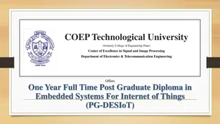
Datapath and Control - BRAM Artix 7 FPGA First page of 7 Series Family Overview: https://www.xilinx.com/support/documentation/data_sheet s/ds180_7Series_Overview.pdf Third page lists quantities how many of these resources our Nexys Video boards have. For reference we are using the XC7A200T chip and the SBG484 package. 4 CSCE 436 Advanced Embedded Systems
Datapath and Control - BRAM In our upcoming Lab2, you will need a large RAM to store 18-bit audio samples streaming in from the Nexys Video board. The Xilinx FPGA on our board, a Artix 7, contains built in block RAMs (BRAMs). You can select of the three main BRAMSconfiguration (BRAM_SDP_MACRO, BRAM_SINGLE_MACRO, BRAM_TDP_MACRO) available in the UNIMACRO library. We will be using a BRAM_SDP_MACRO in our design. According to Vivado Design Suite 7 Series FPGA Libraries Guide: 5 CSCE 436 Advanced Embedded Systems
Datapath and Control - BRAM FPGA devices contain several block RAM memories that can be configured as general-purpose 18Kb or 36Kb RAM/ROM memories. These block RAM memories offer fast and flexible storage of large amounts of on-chip data. Both read and write operations are fully synchronous to the supplied clock(s) of the component. However, READ and WRITE ports can operate fully independently and asynchronously to each other, accessing the same memory array. Byte-enable write operations are possible, and an optional output register can be used to reduce the clock-to-out times of the RAM. 6 CSCE 436 Advanced Embedded Systems
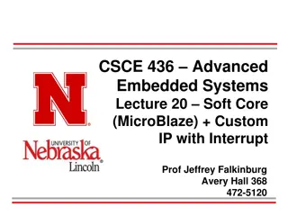
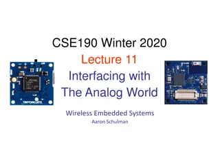
Datapath and Control - BRAM This is a schematic symbol of BRAM memory. Notes: Inputs are on left Outputs are on the right. Left top side - write functions Left bottom - the read functions The three types of BRAMs are highly configurable, but may be overwhelming to the new designer. 7 CSCE 436 Advanced Embedded Systems
Datapath and Control BRAM Example Instantiation ---------------------------------------------------------------------------- -- Reference: Vivado Design Suite 7 Series FPGA Libraries Guide -- UG953 (v 2012.4) July 25, 2012 -- -- Page: ----------------------------------------------------------------------------- sampleMemory: BRAM_SDP_MACRO generic map ( BRAM_SIZE => "18Kb", DEVICE => "7SERIES", DO_REG => 0, INIT => X"000000000000000000", INIT_FILE => "NONE", WRITE_WIDTH => 18, READ_WIDTH => 18, SIM_COLLISION_CHECK => "NONE", -- Collision check enable "ALL", "WARNING_ONLY", SRVAL => X"000000000000000000") -- Set/Reset value for port output 10 -- Target BRAM, "18Kb" or "36Kb" -- Target device: "VIRTEX5", "VIRTEX6", "SPARTAN6, 7SERIES" -- Optional output register disabled -- Initial values on output port -- Not sure how to initialize the RAM from a file -- Valid values are 1-72 (37-72 only valid when BRAM_SIZE="36Kb") -- Valid values are 1-72 (37-72 only valid when BRAM_SIZE="36Kb") "GENERATE_X_ONLY" or "NONE" 8 CSCE 436 Advanced Embedded Systems
Datapath and Control BRAM Instantiation continued port map ( DO => readOutput, RDADDR => vecAddrRead, RDCLK => clk, RST => reset, RDEN => cw(5), REGCE => '1', DI => writeInput, WE => cw(3 downto 2), WRADDR => vecAddrWrite, WRCLK => clk, WREN => cw(4)); -- Output read data port, width defined by READ_WIDTH parameter -- Input address, width defined by port depth -- 1-bit input clock -- active high reset -- read enable -- 1-bit input read output register enable - ignored -- Input data port, width defined by WRITE_WIDTH parameter -- since RAM is byte read, this determines high or low byte -- Input write address, width defined by write port depth -- 1-bit input write clock -- 1-bit input write port enable 9 CSCE 436 Advanced Embedded Systems
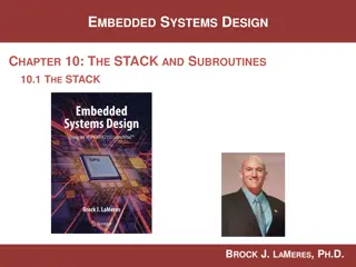
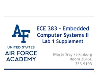
Datapath and Control Class Activity Class Activity: Determine what will happen inside the RAM defined above when subject to the following signals. -- vecAddrRead = vecAddrWrite - 1 -- writeInput <= "10101010101010" & vecAddrWrite(3 downto 0); cw(5) <= '1', '0' after 7 us, '1' after 8 us; -- READ ENABLE cw(4) <= '1', '0' after 3 us, '1' after 4 us; -- WRITE ENABLE cw(3 downto 2) <= "11", "10" after 4 us, "01" after 5 us, "11" after 6us; -- BYTE WRITE ENABLE cw(1 downto 0) <= "01"; -- COUNTER CONTROL 10 CSCE 436 Advanced Embedded Systems
Datapath and Control - BRAM 1023 Addr 0x0 0x1 0x2 0x3 0x4 0x5 0x6 0x7 0x8 0x9 0xA 0xB 0xC 0xD 0xE 0xF writeInput 0x2AAA0 0x2AAA1 WREN=cw(4) WE=cw(3,2) RDEN=cw(5) readOutput 0x2AAA8 11 0x2AAAE CSCE 436 Advanced Embedded Systems
Datapath and Control - Packages Packages are a nice way to hide lots of component declarations Redundancy is one of the main contributors of complexity in software is redundancy. Having an entities declaration in several different architectures is redundant. Pulling all these declarations into one file eliminates this redundancy and make the code much easier to maintain and update. So how do you create a Package? 12 CSCE 436 Advanced Embedded Systems
Datapath and Control - Packages Packages Package for Lab 2 https://cse.unl.edu/~jfalkinburg/cse_courses/2024/436/lecture/code /lab2_pack.vhdl Include this at the top of your file: use work.lab2Parts.all; -- all my components are declared here 13 CSCE 436 Advanced Embedded Systems
2-Line Handshake In most cases, digital systems require data from the external world in order to perform their tasks. In cases where the digital system and the outside word operate on independent clocks, the transfer of data is complicated by the lack of a common clock. To understand how a reliable transfer of data can be performed in this circumstance, consider the following scenario of a producer trying to deliver a packet of candies to a consumer. 14 CSCE 436 Advanced Embedded Systems
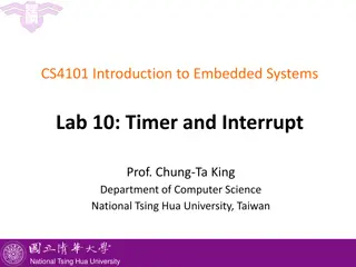
2-Line Handshake Figure 13.2: A timing diagram of a data transfer between a producer and a consumer. 15 CSCE 436 Advanced Embedded Systems
2-Line Handshake This protocol, regardless of who is the producer or consumer, is called a two-line handshake because the communicating agents must have two, coordinating signals Request (REQ) and Acknowledge (ACK) and at least one data line. REQ signal - used by the active agent to signal a readiness to perform a data transfer. ACK signal - used by the passive agent to acknowledge the data has been transferred. 16 CSCE 436 Advanced Embedded Systems
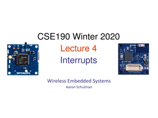
2-Line Handshake An algorithm description of the two-line handshake for a digital circuit which is the passive consumer is shown below. while(REQ==0); // Do nothing but wait register = DATA // Latch the data ACK=1; // Acknowledge the producer while(REQ==1); // Do nothing but wait ACK=0; // Acknowledge the producer In Line 1 and Line 4, the body of the while loops are empty; there is nothing to do but wait. Furthermore, with respect to the external world, the ACK and REQ signals act as status and command bits, respectively. The algorithm above is translated into datapath and control in Figure 13.3. 1. 2. 3. 4. 5. 17 CSCE 436 Advanced Embedded Systems
2-Line Handshake 1. while(REQ==0); // Do nothing but wait register = DATA // Latch the data ACK=1; // Acknowledge the producer while(REQ==1); // Do nothing but wait ACK=0; // Acknowledge the producer 2. 3. 4. 5. Figure 13.3: The datapath and control components required to implement a two-line handshake where the digital system is the passive consumer. 18 CSCE 436 Advanced Embedded Systems
Datapath and Control - Exercise Build a circuit to read in an 8-bit KEY using a two-line handshake; the circuit is a passive consumer. The circuit should search an 18kbx8 RAM, counting the number of words that match KEY. Assume the RAM is preloaded with data and it can respond to a read request with valid data within one clock 1. while(1) { 2. while(REQ == 0); 3. KEY = data; 4. ACK = 1; 5. while(REQ == 1); 6. ACK = 0; 7. match = 0; 8. for(i=0; i<2048; i++) { 9. MBR = RAM[i]; 10. if (MBR == KEY) { 11. match=match+1; 12. } // end if 13. } // end for 14. } // end while 19 CSCE 436 Advanced Embedded Systems
Homework #8 Now lets build the datapath and control using the technique learned in lecture 12. Your homework is to build the control unit for the keyboard scancode reader. 20 CSCE 436 Advanced Embedded Systems
Homework #8 21 CSCE 436 Advanced Embedded Systems