Embedded Systems: Introduction to Input and Output Devices
This material explores the essential concepts related to input and output (I/O) devices in embedded systems. It covers examples of I/O devices, such as keyboards, mice, and disk drives, along with the digital interface between these devices and the CPU. Specific focus is given to the 8251 UART as an I/O device example, explaining its functions and interface with the CPU. Additionally, the content delves into serial communication parameters, I/O primitives, and the concept of busy-wait I/O in embedded systems.

Download Presentation

Please find below an Image/Link to download the presentation.
The content on the website is provided AS IS for your information and personal use only. It may not be sold, licensed, or shared on other websites without obtaining consent from the author. Download presentation by click this link. If you encounter any issues during the download, it is possible that the publisher has removed the file from their server.
E N D
Presentation Transcript
CPUs Chapter 3 COE 306: Introduction to Embedded Systems Dr. Aiman El-Maleh Computer Engineering Department College of Computer Sciences and Engineering King Fahd University of Petroleum and Minerals
Next . . . Input and Output (I/O) Devices Busy-Wait (Polling) I/O Interrupt I/O Supervisor Mode, Exceptions, and Traps Caches and CPUs Memory Management CPU Performance CPU Power Consumption & Management CPUs COE 306 Introduction to Embedded System KFUPM slide 2
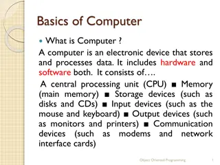
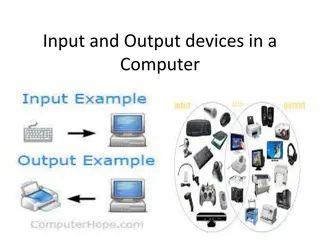
Input and Output (I/O) Devices Examples: keyboard, mouse, disk drive Usually include some non-digital component Typical digital interface to CPU: Data registers hold values that are treated as data by the device, such as the data read or written by a disk. Status registers provide information about the device s operation, such as whether the current transaction has completed. CPUs COE 306 Introduction to Embedded System KFUPM slide 3
I/O Device Example: 8251 UART Universal asynchronous receiver transmitter (UART): provides serial communication 8251 UART functions are integrated into standard PC interface chip Allows many communication parameters to be programmed Characters are transmitted separately CPUs COE 306 Introduction to Embedded System KFUPM slide 4
8251 CPU Interface Serial communication parameters Baud (bit) rate Number of bits per character Parity/no parity Even/odd parity Length of stop bit (1, 1.5, 2 bits) CPUs COE 306 Introduction to Embedded System KFUPM slide 5
8251 Registers CPUs COE 306 Introduction to Embedded System KFUPM slide 6
Input and Output Primitives I/O instructions Separate address space Example: x86 use in and out instructions Memory-mapped I/O An address for each I/O device register Communicate with devices: read/write instructions Common in most architectures CPUs COE 306 Introduction to Embedded System KFUPM slide 7
Busy-Wait I/O I/O devices are slower than CPUs Must finish an I/O operation before starting the next True for both reading and writing Simplest way to program device Use instructions to test when device is ready. Polling Asking an I/O device whether it is finished by reading its status register CPUs COE 306 Introduction to Embedded System KFUPM slide 8
Polling Example Output a string, character by character The device has two registers: one for the character to be written and a status register. When writing, we must set the output status register to 1 to start writing and wait for it to return to 0. .#define OUT_CHAR 0x1000 #define OUT_STATUS 0x1001 char *mystring = Hello, World! ; char *current_char; current_char = mystring; while (* current_char != \0 ){ (* (char *) OUT_CHAR) = *current_char; (* (char *) OUT_STATUS) = 1; while ( (* (char *) OUT_STATUS) != 0); current_char++; } CPUs COE 306 Introduction to Embedded System KFUPM slide 9
Another Polling Example Copy characters from input to output The input device sets its status register to 1 when a new character has been input; we must set the status register back to 0 after the character has been read so that the device is ready to input another character. When writing, we must set the output status register to 1 to start writing and wait for it to return to 0. while (1) { while (* (char *) IN_STATUS == 0); c = * (char *) IN_DATA; * (char *) IN_STATUS=0; * (char *) OUT_DATA = c; * (char *) OUT_STATUS = 1; while (* (char *) OUT_STATUS != 0); } char c; CPUs COE 306 Introduction to Embedded System KFUPM slide 10
Interrupt I/O Busy/wait I/O is very inefficient CPU can t do other work while testing device Hard to do simultaneous I/O Interrupt mechanism 1. I/O device asserts an interrupt request signal 2. CPU asserts interrupt acknowledge signal 3. PC is set to the address of interrupt handler 4. When the interrupt handler finishes, it returns to the foreground program CPUs COE 306 Introduction to Embedded System KFUPM slide 11
Interrupt Example Copy characters from input to output using interrupts What is the limitation of this code? How can we improve it? CPUs COE 306 Introduction to Embedded System KFUPM slide 12
Interrupt I/O with Buffer Copying Characters from Input to Output with Interrupts and Buffers CPUs COE 306 Introduction to Embedded System KFUPM slide 13
Another Interrupt Example Input Device 8-bit status register at address 0xA0 Bit 0 is a data ready flag set whenever new data is received once data is processed, data ready flag must be reset 8-bit data register at address 0xA1 generates an interrupt request upon receiving new data Output Device 8-bit status register at address 0xB0 Bit 0 is a ready to send flag set by device when ready to send data Bit 1 is a transmit enable bit reset by device after each transmission 16-bit data register at address 0xB1 generates an interrupt request when ready to send new data CPUs COE 306 Introduction to Embedded System KFUPM slide 14
Another Interrupt Example Write software that collects 8-bits received through the input device, and accumulates them until the output device becomes ready to send Once the output device becomes ready to send data, the accumulated data is sent using the output device The first data received after sending replaces the previous accumulated data CPUs COE 306 Introduction to Embedded System KFUPM slide 15
Another Interrupt Example #define DEV1_STATUS 0xA0 #define DEV1_DATA 0xA1 #define DEV2_STATUS 0xB0 #define DEV2_DATA 0xB1 short data = 0; // 16-bit data void device1_handler(void) { data += (* (char *) DEV1_DATA); (* (char *) DEV1_STATUS) &= 0xfe; // reset data ready flag } void device2_handler(void) { (* (short *) DEV2_DATA) = data; (* (char *) DEV2_STATUS) |= 2; // transmit enable data = 0; } CPUs COE 306 Introduction to Embedded System KFUPM slide 16
Interrupts vs. Polling I/O Polling takes CPU time even when no requests pending overhead may be reduced at expense of response time Interrupts no overhead when no requests pending facilitate concurrency can be hard to debug What if ISR does not save & restore a used register? Foreground program can exhibit mysterious bugs Bugs will be hard to repeat---depend on interrupt timing CPUs COE 306 Introduction to Embedded System KFUPM slide 17
Interrupt Implementation The CPU checks the interrupt request line before executing every instruction If asserted, the CPU sets PC to the beginning of the interrupt handler The interrupt handler code can reside anywhere in memory. Its starting address is stored in a predefined location CPU s interrupt mechanism resembles its subroutine function High-level language interface for interrupt handlers depends on CPU and compiler CPUs COE 306 Introduction to Embedded System KFUPM slide 18
Supporting Multiple I/O Devices- Priorities Interrupt Priorities allow the CPU to recognize some interrupts as more important than others Multiple interrupt request signals, e.g. L1, L2, . . . , Ln Lower number signals have higher priority Interrupt acknowledge signal carries the request number A device knows its request is accepted by seeing its priority number on the interrupt acknowledge lines Priorities are set by connecting request lines Changing priorities requires hardware modification CPUs COE 306 Introduction to Embedded System KFUPM slide 19
Multiple Interrupt Request Lines log2 n CPUs COE 306 Introduction to Embedded System KFUPM slide 20
Interrupt Priorities Interrupt Masking A lower-priority interrupt does not occur while a higher-priority interrupt is being handled Priority register: holds priority of currently handled interrupt Non-Maskable Interrupt (NMI) The highest-priority interrupt Usually reserved for interrupts caused by power failures Typically, up to 8 priorities How to support more than 8 devices? CPUs COE 306 Introduction to Embedded System KFUPM slide 21
Interrupt Priorities More priority levels can be added with external logic When more than one device are connected to the same interrupt line, the CPU does not know which device caused the interrupt The handler uses software polling to check the status of each device to know the device who requested the interrupt It can assign priority among the requesting devices by arranging the order of checking their status CPUs COE 306 Introduction to Embedded System KFUPM slide 22
Example: Prioritized I/O Assume that we have devices A, B, and C. A has priority 1 (highest priority), B priority 2, and C priority 3. CPUs COE 306 Introduction to Embedded System KFUPM slide 23
Supporting Multiple I/O Devices- Vectors Interrupt Vectors allow interrupting device to specify its handler Requires additional interrupt vector lines from device to CPU Device sends interrupt vector after its request is acknowledged CPU uses interrupt vector as an index to a memory table The location referenced in the interrupt vector table by the vector number specifies the address of the handler Each device stores its vector number It can be changed without modifying the system software CPUs COE 306 Introduction to Embedded System KFUPM slide 24
Interrupt Sequence CPU acknowledges request Device sends vector CPU calls handler Handler Software processes request CPU restores state to foreground program CPUs COE 306 Introduction to Embedded System KFUPM slide 25
Interrupt Overhead Interrupt Overhead Branch penalty Automatically storing and restoring CPU registers Acknowledging interrupts and waiting for vectors Additional saving and restoring of registers by the handler Returning incurs another branch penalty Optimizing Interrupt Handlers Minimize number of registers used by the handler that need to be saved and restored Requires writing interrupt handlers in assembly CPUs COE 306 Introduction to Embedded System KFUPM slide 26
Interrupts in ARM7 Interrupt requests (IRQ) Fast interrupt requests (FIQ) higher priority Interrupt table: address 0 Table entries: subroutine calls to the handlers Interrupt response latency: 4 27 cycles Responding to an interrupt request Save PC Copy CPSR to SPSR Set CPSR for the interrupt Set PC to the interrupt vector Leaving the interrupt handler Restore PC Restore CPSR from SPSR Clear interrupt disable flag CPUs COE 306 Introduction to Embedded System KFUPM slide 27
Supervisor Mode Supervisor mode is an execution mode on some processors which enables execution of all instructions, including privileged instructions. It may also give access to a different address space, to memory management hardware and to other peripherals. This is the mode in which the operating system usually runs. Supervisor mode has privileges that user modes do not, e.g. MMU control ARM Supervisor Mode Instruction: SWI Similar to interrupts, but uses special registers CPUs COE 306 Introduction to Embedded System KFUPM slide 28
Exceptions Exception is an internally detected error Examples: division by zero, undefined instructions, illegal memory access Exceptions are synchronous with instructions but unpredictable Checked during execution; handled like interrupts Require prioritization and vectoring Priorities and vector numbers are usually fixed by the architecture Vectors allow user-provided handlers CPUs COE 306 Introduction to Embedded System KFUPM slide 29
Traps A trap is a software interrupt; an instruction that explicitly generates an exception The main purpose of a trap is to provide a fixed subroutine that various programs can call without having to actually know the run-time address MS-DOS is the perfect example. The int 21h instruction is an example of a trap invocation to transfer control to DOS entry point ARM uses SWI instruction for traps Example: entering supervisor mode CPUs COE 306 Introduction to Embedded System KFUPM slide 30
Co-Processors Reserved op-codes for co-processor operations CPU passes co-processor instructions to co-processor Co-processors have access to CPU registers CPU may suspend or continue execution while waiting for co-processors A co-processor instruction without a co-processor Illegal instruction trap Trap handler can emulate the instruction in software Software emulation is slow, but provides compatibility ARM supports up to 16 co-processors Example: floating-point unit CPUs COE 306 Introduction to Embedded System KFUPM slide 31
Memory System Overview The memory system comprises cache and main memory Caches increase the average performance of the memory system Memory Management Units (MMUs) perform address translations that provide a larger virtual memory space in a small physical memory CPUs COE 306 Introduction to Embedded System KFUPM slide 32
Caches Cache memory is a small fast memory that holds copies of some of the contents of main memory May have caches for: instructions; data; data + instructions (unified). It speeds up average memory access time It increases the variability of memory access time accesses in the cache will be fast, access to locations not cached will be slow It is effective when the CPU is using only a relatively small set of memory locations at any one time; the set of active locations is often called the working set CPUs COE 306 Introduction to Embedded System KFUPM slide 33
Cache and Main Memory Cache hit: required location is in cache Cache miss: required location is not in cache Types of cache misses Compulsory (Cold) miss: occurs the first time a location is accessed Capacity miss: caused by a too-large working set Conflict miss: two memory locations map to the same cache location h = cache hit rate; cache hit probability tcache = cache access time, tmain = memory access time Average memory access time: tavg = tcache + (1-h) tmain CPUs COE 306 Introduction to Embedded System KFUPM slide 34
Multiple Levels of Cache L1 cache: fastest; closest to CPU; usually on-chip L2 cache: feeds L1 cache; usually off-chip h1 = L1 cache hit rate. h2 = L2 cache hit rate. Average memory access time tavg = tL1 + (1-h1)tL2 + (1-h1)(1-h2)tmain CPUs COE 306 Introduction to Embedded System KFUPM slide 35
Cache Organizations & Policies Cache organizations Fully-associative: any memory location can be stored anywhere in the cache (almost never implemented). Direct-mapped: each memory location maps onto one cache entry. N-way set-associative: each memory location maps into one of n sets. Replacement policy: strategy for choosing which cache entry to remove to make room for new memory location Two popular strategies: Random, Least-recently used (LRU) Write operations Write-through: immediately copy write to main memory Write-back: write to main memory only when location is removed from cache CPUs COE 306 Introduction to Embedded System KFUPM slide 36
Example Cache Implementations ARM600: 4-KB, 64-way unified cache StrongARM 16 Kbyte, 32-way, 32-byte block instruction cache. 16 Kbyte, 32-way, 32-byte block data cache (write-back). C5510: 16-KB instruction cache, 2-way, 4x32-bit words per line CPUs COE 306 Introduction to Embedded System KFUPM slide 37
Virtual Memory Virtual Memory: is imaginary memory; it gives you the illusion of a memory arrangement that s not physically there Logical Address: The program s abstract address space Physical Address: Actual location in physical memory (RAM) Memory management unit (MMU) translates addresses CPUs COE 306 Introduction to Embedded System KFUPM slide 38
Advantages of Virtual Memory Flexibility: Decouples a process view of memory from physical memory Process memory can be moved and resized based on run-time behavior A process can address more or less memory than physically installed Abstraction: A process views memory as a single contiguous, private address space (virtual memory) Efficiency: Processes can be allocated different amounts of memory; Better utilization of physical memory Protection: A process cannot access a memory address of another process CPUs COE 306 Introduction to Embedded System KFUPM slide 39
Memory Management Unit Tasks Allows programs to move in physical memory during execution Allows virtual memory: memory images kept in secondary storage images returned to main memory on demand during execution Page fault: request for location not resident in memory CPUs COE 306 Introduction to Embedded System KFUPM slide 40
Address Translation Requires some sort of register/table to allow arbitrary mappings of logical to physical addresses. Two basic schemes: segmentation paging Segmentation and paging can be combined (x86) CPUs COE 306 Introduction to Embedded System KFUPM slide 41
Segmentation Segment Large, arbitrarily-sized region of memory Described by a start address and a size Segment address translation CPUs COE 306 Introduction to Embedded System KFUPM slide 42
Paging Paging divides the linear address space into Fixed-sized blocks called pages, e.g. 4 KB pages Operating system allocates main memory for pages Pages can be spread all over main memory Pages in main memory can belong to different programs If main memory is full then pages are stored on the hard disk OS has a Virtual Memory Manager (VMM) Uses page tables to map the pages of each running program Manages the loading and unloading of pages As a program is running, CPU does address translation Page fault: issued by CPU when page is not in memory CPUs COE 306 Introduction to Embedded System KFUPM slide 43
Paging contd Main Memory The operating system uses page tables to map the pages in the linear virtual address space onto main memory linear virtual address linear virtual address . . . Page m Page n space of Program 1 space of Program 2 . . . . . . Page 2 Page 2 Page 1 Page 1 Page 0 Page 0 Hard Disk The operating system swaps pages between memory and the hard disk Pages that cannot fit in main memory are stored on the hard disk Each running program has its own page table As a program is running, the processor translates the linear virtual addresses onto real memory (called also physical) addresses CPUs COE 306 Introduction to Embedded System KFUPM slide 44
Paging Page: Small, equally-sized region of memory Simpler hardware for address translation Allows fragmentation Page address translation CPUs COE 306 Introduction to Embedded System KFUPM slide 45
The Page Table Typically, pages are 512 B 4 KB large page table The page table is in memory Address translation requires memory access Flat vs. tree page table Why use a tree page table? How to speed up address translation? Use a cache; TLB: Translation Lookaside Buffer Page Table Entry components Base address Present bit; Dirty bit (page content has been modified) Permission bits CPUs COE 306 Introduction to Embedded System KFUPM slide 46
Multi-Level Page Tables Given: 4KB (212) page size 32-bit address space 4-byte page table entry (PTE) Problem: Would need a 4 MB page table! 220 *4 bytes Per-process Common solution Multi-level page tables E.g., 2-level table (Pentium) Level-1 table: 1024 entries, each of which points to a Level 2 page table Level-2 table: 1024 entries, each of which points to a page CPUs COE 306 Introduction to Embedded System KFUPM slide 47
MMU in ARM Optional Provides address translation and memory protection Supported types of memory regions: Section: 1 MB Large page: 64 KB Small page: 4 KB An address is marked as section-mapped or page- mapped Two-level address translation CPUs COE 306 Introduction to Embedded System KFUPM slide 48
Two-Level Address Translation CPUs COE 306 Introduction to Embedded System KFUPM slide 49
Virtual Memory System Example Logical address is 32 bits, page size is 4 kB. Consider the given page table below: How many address bits are used to identify the page (page number)? How many virtual pages can there be? How many address bits are used for the offset within a page? Given the logical address 0x4365, what is the page number? what is the offset? What is the corresponding physical address? Which is larger: virtual memory or physical memory? CPUs COE 306 Introduction to Embedded System KFUPM slide 50


 Devices")