Understanding Timers and Time Tracking in Embedded Systems
Explore the importance of timers in embedded systems for tracking time, managing interrupts, and ensuring accurate timekeeping. Learn about different peripherals used, such as real-time clocks and processor timers, to handle tasks like updating UI elements, triggering alarms, and measuring intervals. Discover the internal structure of timer peripherals and their role in time management in wireless embedded systems.
Download Presentation

Please find below an Image/Link to download the presentation.
The content on the website is provided AS IS for your information and personal use only. It may not be sold, licensed, or shared on other websites without obtaining consent from the author. Download presentation by click this link. If you encounter any issues during the download, it is possible that the publisher has removed the file from their server.
E N D
Presentation Transcript
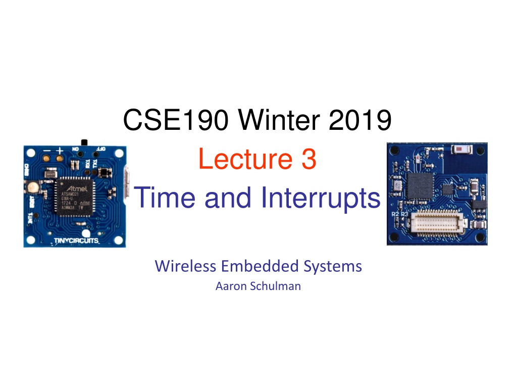
CSE190 Winter 2019 Lecture 3 Time and Interrupts Wireless Embedded Systems Aaron Schulman
What time is the Apple Watch tracking? How often | Granularity Clock (all the time | sec) Alarm (all the time | sec) Stopwatch (when open | msec) Sync (all the time | sec) UI (when open | msec) Buzzer (when buzzing | msec) WiFi (when communicating | usec)
Why do we need timers? In this project, we need timers for Determining when to change the bits 20 Hz means change bits every 50 milliseconds How to measure 50 ms? Option 1: Use the timer hardware to let you know when 50 ms has passed. Option 2: Count how many processor cycles it would take to equal 50 ms.
Why do we need timers? In general, why do we need timers? What time is it now? How much time has elapsed since I last checked? Let me know when this much time passes. When did this external input occur?
What peripherals do we use to track time? (all the time | sec) - [Alarm, Sync] 32-bit Real time clock (RTC) peripheral with interrupts (when open/buzzing | msec) - [Stopwatch, UI, Buzzer] Processor s timer peripheral with interrupts (when communicating | usec) - [WiFi] WiFi chip s internal timer peripheral with interrupts
What peripherals do we use to track time? (all the time | sec) - [Alarm, Sync] 32-bit Real time clock (RTC) peripheral with interrupts The term is used to avoid confusion with ordinary hardware clocks which are only signals that govern digital electronics, and do not count time in human units. (when open/buzzing | msec) - [Stopwatch, UI, Buzzer] Processor s timer peripheral with interrupts (when communicating | usec) - [WiFi] WiFi chip s internal timer peripheral with interrupts
The internal structure of a timer peripheral Application Software Timer Abstractions and Virtualization Low-Level Timer Device Drivers Software R/W R/W R/W Hardware Compare Counter Capture The purpose of the prescaler is to allow the timer to be clocked at the rate a user desires. Prescaler Clock Driver Internal External Xtal/Osc Frequency depends on the attached oscillator device Figure adapted from Prabal Dutta s EE373 slides
How does the number in the counter register correspond to wall clock time? Frequency (Hz) = Cycles / Second 1 / Frequency (Hz) = Seconds / Cycle The counter is incremented once per cycle. You read 100 from the counter register which is clocked by a 1 MHz oscillator. How much time has passed since the counter was reset?
How should we choose the OSC frequency? For timers, there will often be a tradeoff between resolution (high resolution requires a high clock rate) and range (high clock rates cause the timer to overflow more quickly). 1MHz OSC: resolution = 1 / 1e6 second = 1us 10MHz OSC: resolution = 1/10e6 second = 0.1us 16-bits timer: 1MHz OSC: max range = 1 / 1e6 * 2^16 = 65.536ms 10MHz OSC: max range = 1/10e6 * 2^16 = 6.5536ms
How does a firmware developer use the compare register? Application Software 1. Stop the timer 2. Set the compare register with the time it should fire 3. Reset the counter 4. Start the timer 5. Wait for the counter to reach the compare (via interrupt or check status reg) Timer Abstractions and Virtualization Low-Level Timer Device Drivers So#ware( ( Hardware( R/W( R/W( R/W( Compare Counter Capture Prescaler Clock Driver Internal( ( External( Xtal/Osc
How does a firmware developer use the capture register? 1. 2. Stop the timer Setup the timer to capture when a particular event occurs (e.g., change of GPIO pin) Reset the counter Start the timer Wait for the counter to reach a capture event (via interrupt or check status reg) Application Software Timer Abstractions and Virtualization Low-Level Timer Device Drivers So#ware( ( Hardware( 3. 4. 5. R/W( R/W( R/W( Compare Counter Capture Prescaler Clock Driver Internal( ( External( Xtal/Osc
The internal structure of a Real Time Clock (RTC) Note: RTCs have their own oscillator. Why is it 32,768 kHz? Figure adapted from Prabal Dutta s EE373 slides
The internal structure of a Real Time Clock (RTC) Note: RTCs have their own oscillator. Why is it 32,768 kHz? The reason the 32,768 Hz resonator has become so common is due to a compromise between the large physical size of low frequency crystals and the large current drain of high frequency crystals. Figure adapted from Prabal Dutta s EE373 slides
Interrupts How peripherals notify the CPU that their state just changed. Example: A button just pressed
Interrupts Definition An event external to the currently executing process that causes a change in the normal flow of instruction execution; usually generated by hardware devices external to the CPU. Key point is that interrupts are asynchronous w.r.t. current process Typically indicate that some device needs service Slides from Angela Demke Brown CSC 469H1F
Why interrupts? MCUs have many external peripherals Keyboard, mouse, screen, disk drives, scanner, printer, sound card, camera, etc. These devices occasionally need CPU service But we can t predict when We want to keep the CPU busy (or asleep) between events Need a way for CPU to find out devices need attention Slides from Angela Demke Brown CSC 469H1F
Possible Solution: Polling CPU periodically checks each device to see if it needs service Polling is like picking up your phone every few seconds to see if you have a call. Slides from Angela Demke Brown CSC 469H1F
Possible Solution: Polling CPU periodically checks each device to see if it needs service Polling is like picking up your phone every few seconds to see if you have a call. Cons: takes CPU time even when no requests pending Pros: can be efficient if events arrive rapidly Slides from Angela Demke Brown CSC 469H1F
Alternative: Interrupts Give each device a wire (interrupt line) that it can use to signal the processor
Alternative: Interrupts Give each device a wire (interrupt line) that it can use to signal the processor When interrupt signaled, processor executes a routine called an interrupt handler to deal with the interrupt No overhead when no requests pending
How do interrupts work? Interrupt Clear interrupt Peripheral 1 Peripheral P sends int X ACK P s int X Execute P s X handler ACK P s int X Peripheral 2 Interrupt controller CPU Peripheral 3 What is the benefit of having a separate controller for interrupts? Peripheral 4
The Interrupt controller Handles simultaneous interrupts o Receives interrupts while the CPU handles interrupts Maintains interrupt flags o CPU can poll interrupt flags instead of jumping to a interrupt handler Multiplexes many wires to few wires CPU doesn t need a interrupt wire to each peripheral Fun fact: Interrupt controllers used to be separate chips! Intel 8259A IRQ chip Imageby Nixdorf - Own work
How to use interrupts 1. Tell the peripheral which interrupts you want it to output. 2. Tell the interrupt controller what your priority is for this interrupt. 3. Tell the processor where the interrupt handler is for that interrupt. 4. When the interrupt handler fires, do your business then clear the int.
CPU execution of interrupt handlers INTERRUPT 1. Wait for instruction to end 2. Push the program counter to the stack 3. Push all active registers to the stack 4. Jump to the interrupt handler in the interrupt vector 5. Pop the program counter off of the stack
