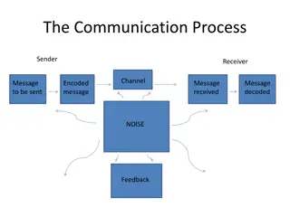
Comparison of SPI and I2C Communication in Embedded Systems

SPI and I2C are two common communication protocols used in embedded systems. SPI offers fast and easy point-to-point connections with no addressing needed, while I2C allows connecting multiple peripherals with just two wires. SPI has pros such as fast data transfer but cons like complexity with multiple slaves. On the other hand, I2C has lower overhead but slower bus speeds. Both protocols have specific timings and clocking modes that must be followed for successful communication.

Download Presentation

Please find below an Image/Link to download the presentation.
The content on the website is provided AS IS for your information and personal use only. It may not be sold, licensed, or shared on other websites without obtaining consent from the author. Download presentation by click this link. If you encounter any issues during the download, it is possible that the publisher has removed the file from their server.
E N D
Presentation Transcript
CSE190 Winter 2020 Lecture 7 SPI and I2C Wireless Embedded Systems Aaron Schulman
SPI clocking: there is no standard way Four clocking modes Two phases Two polarities Master and selected slave must be in the same mode During transfers with slaves A and B, Master must Configure clock to Slave A s clock mode Select Slave A Do transfer Deselect Slave A Configure clock to Slave B s clock mode Select Slave B Do transfer Deselect Slave B Master reconfigures clock mode on-the-fly! 3
SPI timing diagram Timing Diagram Showing Clock polarities and phases http://www.maxim-ic.com.cn/images/appnotes/3078/3078Fig02.gif 4
SPI Pros and Cons Pros: Fast and easy Fast for point-to-point connections Easily allows streaming/Constant data inflow No addressing/Simple to implement Everyone supports it Cons: SS makes multiple slaves very complicated No acknowledgement ability No inherent arbitration No flow control 5
I2C bus (in our projects) Communication with the accelerometer Read acceleration values and configure interrupts Pros Two wires bus that can connect multiple peripherals with the MCU Cons Overhead is significantly higher, and bus is slower
I2C Details Two lines Serial data line (SDA) Serial clock line (SCL) Only two wires for connecting multiple devices
I2C Details Each I2C device recognized by a unique address Each I2C device can be either a transmitter or receiver I2C devices can be masters or slaves for a data transfer Master (usually a microcontroller): Initiates a data transfer on the bus, generates the clock signals to permit that transfer, and terminates the transfer Slave: Any device addressed by the master at that time
How can any device transfer or receive on the same two wires? Pull ups and high-impedance mode pins Wires default to being on , any device can make a wire go off . This is super clever. SPI and UART can t do this, why?
Bit Transfer on the I2C Bus In normal data transfer, the data line only changes state when the clock is low SDA SCL Data line stable; Data valid Change of data allowed 10 of 40
Start and Stop Conditions A transition of the data line while the clock line is high is defined as either a start or a stop condition. Both start and stop conditions are generated by the bus master The bus is considered busy after a start condition, until a stop condition occurs SDA SDA SCL SCL Start Condition Stop Condition 11 of 40
I2C Addressing Each node has a unique 7 (or 10) bit address Peripherals often have fixed and programmable address portions Addresses starting with 0000 or 1111 have special functions:- 0000000 Is a General Call Address 0000001 Is a Null (CBUS) Address 1111XXX Address Extension 1111111 Address Extension Next Bytes are the Actual Address 12 of 40
I2C-Connected System Example I2C-connected system with two microcontrollers (Source: I2C Specification, Philips)
Master-Slave Relationships Who is the master? master-transmitters master-receivers Suppose microcontroller A wants to send information to microcontroller B A (master) addresses B (slave) A (master-transmitter), sends data to B (slave-receiver) A terminates the transfer. If microcontroller A wants to receive information from microcontroller B A (master) addresses microcontroller B (slave) A (master-receiver) receives data from B (slave-transmitter) A terminates the transfer In both cases, the master (microcontroller A) generates the timing and terminates the transfer
Exercise: How fast can I2C run? How fast can you run it? Assumptions 0 s are driven 1 s are pulled up Some working figures Rp= 10 k Ccap = 100 pF VDD = 5 V Vin_high = 3.5 V Recall for RC circuit Vcap(t) = VDD(1-e-t/ ) Where = RC 15
Exercise: Bus bit rate vs Useful data rate An I2C transactions involves the following bits <S><A6:A0><R/W><A><D7:D0><A><F> Which of these actually carries useful data? <S><A6:A0><R/W><A><D7:D0><A><F> So, if a bus runs at 400 kHz What is the clock period? What is the data throughput (i.e. data-bits/second)? What is the bus efficiency ? 16
How to operate the accelerometer? Accel I2C register 1 register 2 . MCU I2C Springs https://www.youtube.com/watch?v=eqZgxR6eRjo


")